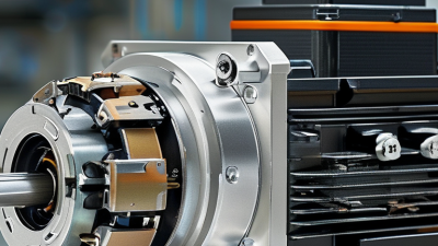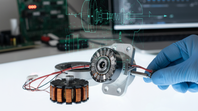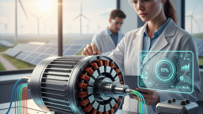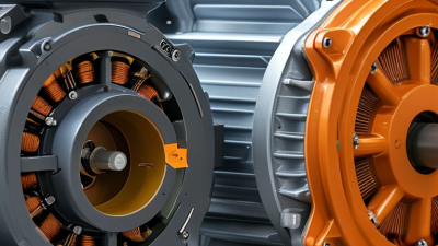
A permanent magnet stepper motor turns electrical pulses into controlled angular movement. Its rotor contains a permanent magnet, while the stator carries carefully arranged coils. When the driver energizes each phase, the rotor moves toward the changing magnetic field. This creates a sequence of precise steps rather than continuous rotation.
Dr. Takashi Kenjo, a respected author on stepping-motor technology, described the operating principle this way: “A step motor converts electrical pulses into mechanical movement.” That sentence remains useful because it connects the circuit to the physical result. Each pulse can represent a defined angle, such as 7.5 or 1.8 degrees. Microstepping can make motion appear smoother, although it does not always create equal mechanical accuracy. That distinction is often overlooked.
This article explains what a permanent magnet stepper motor is, how its magnetic structure works, and where engineers commonly use it. Printers, small positioning tables, camera mechanisms, and low-power automation systems may all benefit from its simple control method. The motor can hold its position without a feedback sensor, but the load must remain within its torque limits. Excessive acceleration, friction, or a sudden load may cause missed steps. It may also produce audible vibration and heat.
That is the practical compromise.
A permanent magnet stepper motor is not automatically the best choice for every motion system. Its strengths include low cost, straightforward control, and useful holding torque. Its weaknesses include resonance, limited high-speed performance, and possible position loss without feedback. Understanding both sides helps readers select the motor more responsibly.
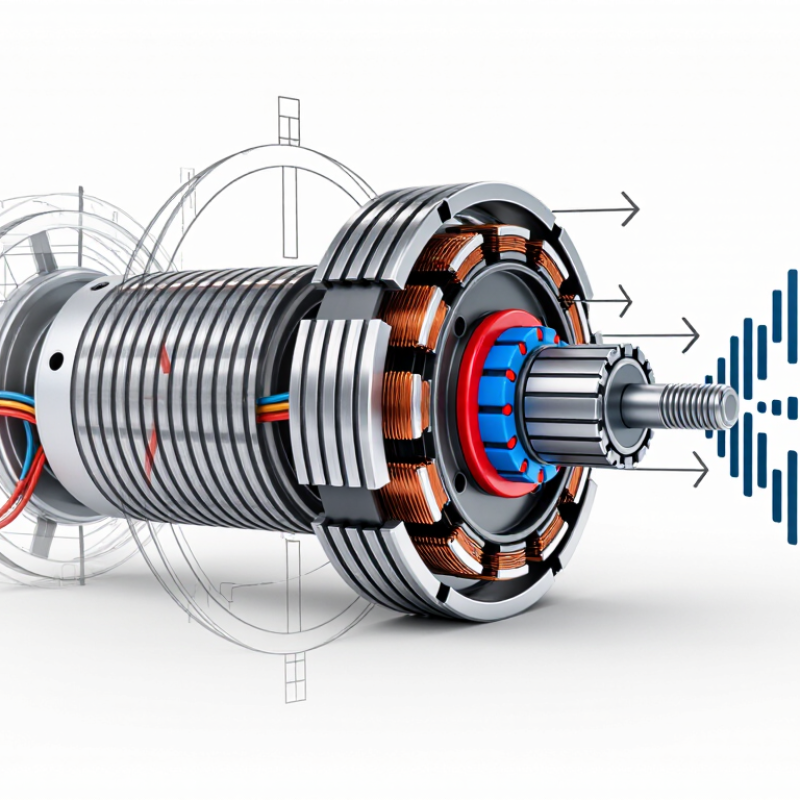
A permanent magnet stepper motor is an electromechanical device that converts electrical pulses into controlled angular movement. Its rotor contains permanent magnets, while the stationary stator carries several energized windings. Unlike a conventional motor, it is designed to move in distinct steps rather than rotate continuously.
The operating principle is straightforward. A controller sends current to selected stator coils. These coils create magnetic fields that attract or repel the rotor magnets. When the energized phase changes, the rotor moves toward the next stable position. Repeating this sequence produces rotation. The pulse frequency determines speed, while the number of pulses determines travel distance. Direction changes when the phase sequence is reversed.
In practical equipment, this behavior supports positioning in small mechanisms, instrument drives, and compact automation systems. A useful technical check is holding torque: with power applied, the shaft should resist external movement. However, the motor can lose synchronism if acceleration is too high or the load suddenly increases. The word “permanent” can also mislead. It describes the rotor magnets, not unlimited performance. Heat, vibration, friction, and incorrect current settings still affect operation. This basic explanation is accurate, but real motion is less tidy than the diagram suggests. Microstepping may improve smoothness, although it does not always increase absolute positioning accuracy.
A permanent magnet stepper motor converts electrical pulses into controlled angular movement. Its rotor contains a permanently magnetized core, usually with multiple north and south poles. The stator surrounds it with toothed steel laminations and copper windings. When the driver energizes each phase, the stator teeth attract opposite rotor poles. The shaft then moves through a defined step angle.
The air gap matters. Too wide, and torque falls. Too narrow, and assembly errors may cause rubbing. Bearings support the shaft, while the housing protects the windings and maintains alignment. A rear cover commonly holds the connector and position hardware. Some designs use a 1.8-degree step angle, producing 200 full steps per revolution. Microstepping can create smoother motion, though it does not guarantee equal mechanical accuracy.
The U.S. Department of Energy’s motor-systems report estimates that motor-driven equipment consumes about 46% of global electricity. This explains the value of reducing heat and wasted current, even in small motion systems. A 2024 Fortune Business Insights report projects the global stepper motor market to exceed 7 billion dollars by 2032. Demand is linked to automation, medical equipment, and compact positioning systems.
The design is elegant, but not flawless. Holding torque can create heat during standstill. Small errors become heat. In practical testing, engineers should inspect phase resistance, shaft play, and temperature rise. One overlooked detail can weaken the entire motion profile.
What Is a Permanent Magnet Stepper Motor?
A permanent magnet stepper motor creates stepwise rotation by switching current through several stator coils. Its rotor contains permanent magnetic poles. Each energized coil produces a magnetic field, pulling the rotor toward a new alignment. The controller repeats this sequence, turning electrical pulses into measured movement. A common 1.8-degree motor needs 200 full steps for one revolution. That movement is predictable, but not perfectly smooth.
Microstepping divides each full step into smaller current changes. It reduces vibration and audible noise, although it cannot guarantee equal mechanical accuracy. The motor can also lose position when its load exceeds available torque. This detail matters in printers, valves, and compact automation systems. A 2023 U.S. Department of Energy motor-systems assessment reported that motor-driven equipment uses about 46% of manufacturing electricity. Stepper motors are not always the most efficient choice, especially when they hold position continuously. Grand View Research has projected steady growth in the global stepper motor market, reflecting demand for precise, compact motion systems.
Tips: Match the motor’s holding torque with a safety margin. Check torque at the intended speed, not only at rest. Use acceleration ramps to prevent missed steps. Keep wiring phases correct. A reversed phase connection may cause shaking instead of rotation. Real testing remains essential; datasheets rarely show every load, temperature, or resonance problem.
| Data Dimension | Typical Data or Feature | How It Relates to Stepwise Rotation | Engineering Notes |
|---|---|---|---|
| Motor Type | Permanent magnet stepper motor | A permanent-magnet rotor moves in discrete angular increments as the stator windings are energized in sequence. | It is generally simpler than a hybrid stepper motor because the rotor normally has no toothed iron structure. |
| Rotor Construction | Permanent magnet rotor | The rotor has fixed magnetic north and south poles that align with the active stator magnetic field. | The rotor does not require electrical excitation, so there is no rotor winding or slip-ring connection. |
| Stator Construction | Laminated magnetic core with two or more phase windings | Each energized phase creates a magnetic field that attracts or repels the rotor poles. | Laminated steel reduces eddy-current losses during repeated switching. |
| Common Phase Arrangement | Two-phase or four-phase winding configuration | The controller changes the current path from one phase to the next to move the magnetic field around the stator. | The required driver depends on the winding configuration and whether the motor is unipolar or bipolar. |
| Typical Step Angle | 7.5° to 15° per full step | Each command pulse advances the rotor by a defined mechanical angle. | The actual angle depends on the number of rotor poles, stator poles, and winding arrangement. |
| Steps per Revolution | 24 to 48 full steps per revolution | The number of full steps is calculated as 360° divided by the full-step angle. | For example, a 7.5° motor provides 48 full steps per revolution. |
| Rotation Sequence | Phase A → Phase B → Phase A reverse → Phase B reverse | A repeated phase sequence produces forward rotation; reversing the sequence produces reverse rotation. | The exact sequence varies with the driver and winding connection. |
| Control Signal | Digital step pulses and a direction command | Each valid step pulse requests one motor increment, while the direction signal determines the rotation direction. | A dedicated driver is normally required to regulate winding current and switch the phases. |
| Microstepping | Possible with a suitable current-controlled driver | The driver divides a full step into smaller current vectors, creating smaller commanded movements and smoother rotation. | Microstepping improves smoothness but does not always provide proportional increases in absolute positioning accuracy or torque. |
| Holding Torque | Typically lower than that of a similarly sized hybrid stepper motor | When energized, the rotor resists displacement because it is magnetically aligned with the stator field. | Holding torque depends on motor size, winding current, magnetic material, air gap, and temperature. |
| Detent Torque | Present even when the windings are unpowered | The permanent magnet rotor is naturally attracted to preferred magnetic positions in the stator. | Detent torque helps prevent free rotation but is normally much lower than energized holding torque. |
| Positioning Method | Open-loop pulse counting | The controller estimates shaft position by counting commanded steps rather than measuring the shaft directly. | An encoder may be added when load disturbances or missed-step detection must be monitored. |
| Speed Behavior | High low-speed torque; torque decreases as speed increases | At higher step rates, winding inductance limits how quickly current can rise and fall. | Acceleration ramps help prevent loss of synchronism during starting, stopping, or rapid speed changes. |
| Resonance Sensitivity | Can experience vibration in specific speed ranges | The pulsed magnetic torque can interact with the rotor's mechanical natural frequency. | Damping, microstepping, proper acceleration control, and suitable load selection can reduce resonance. |
| Typical Operating Voltage | Motor winding ratings commonly range from about 3 V to 24 V | The driver may use a higher supply voltage than the winding's rated voltage to force current into the coils quickly. | The driver must limit current to prevent overheating and winding damage. |
| Typical Phase Current | Approximately 0.1 A to 2 A for many small and medium motors | Higher phase current generally increases available torque until thermal and magnetic limits are reached. | The correct value must be taken from the motor's electrical specifications rather than estimated from size alone. |
| Direction Reversal | Achieved by reversing the phase excitation order | Changing the order of the magnetic field positions makes the rotor follow the field in the opposite direction. | Reversing one phase winding's polarity can also reverse rotation, depending on the connection. |
| Advantages | Simple construction, low cost, good low-speed control, and useful holding torque | The motor can produce controlled incremental motion without a mechanical commutator or brushes. | Its uncomplicated structure is suitable for indicators, small positioning systems, instruments, and light automation. |
| Limitations | Limited high-speed torque, vibration, heating, and possible missed steps | If the commanded step rate or load exceeds the available torque, the rotor may fail to follow the rotating magnetic field. | A proper load, acceleration profile, driver, and thermal design are essential for reliable operation. |
| Basic Operating Principle | The rotor repeatedly aligns with successive stator magnetic fields | Electrical switching creates a rotating magnetic field in discrete positions, and the permanent magnet rotor follows it one step at a time. | The motor converts electrical pulse sequences into predictable angular displacement rather than continuous asynchronous rotation. |
A permanent magnet stepper motor uses a magnetized rotor and energized stator coils. The rotor moves in defined increments as the controller changes the magnetic field. This design provides predictable positioning without brushes or mechanical commutators. It suits compact feeders, small valves, camera mechanisms, and light automation equipment.
Step angle is a core specification. Common values include 7.5 or 15 degrees, while smaller steps require more control pulses. Holding torque describes the force available when the shaft is stopped and powered. It does not guarantee equal torque during motion. Pull-out torque shows the highest load the motor can handle before losing synchronization. That value usually falls as speed increases.
Rated voltage and phase current affect heating, torque, and driver selection. A motor rated for 12 volts may still require current control, not simple voltage switching. Check phase resistance, inductance, winding connection, and maximum temperature. A metal housing can become warm during normal operation.
Permanent magnet stepper motors often perform best at low or moderate speeds. Resonance may cause vibration near particular operating ranges. Microstepping can reduce noise and improve smoothness, but it cannot create unlimited positioning accuracy. Mechanical load, backlash, shaft alignment, and temperature also influence the final result. A datasheet may appear exact, yet real machines are less tidy. Testing the motor with the actual load is still necessary. A small safety margin is wise, though it should be based on measured torque rather than guesswork.
What Is a Permanent Magnet Stepper Motor?
Common Applications and Selection Considerations
A permanent magnet stepper motor uses a magnetized rotor and energized stator coils. Each electrical pulse moves the rotor through a defined angle. This design provides simple positioning without an encoder in many low-speed systems. Its construction is compact, economical, and relatively easy to control. However, it is not automatically the best choice for every motion task.
Common applications include compact printers, valve actuators, laboratory instruments, camera mechanisms, and small conveyor systems. These machines often need repeatable movement, moderate torque, and controlled stopping. According to Grand View Research’s 2024 Stepper Motor Market report, the global market was valued at about 4.4 billion US dollars in 2023. The report also projects continued growth through 2030, supported by automation and precision equipment. Market growth does not remove engineering trade-offs.
Selection should begin with load torque, speed, step angle, supply voltage, and duty cycle. A motor may hold position well but lose torque sharply at higher speeds. Heat is another practical concern. In a confined enclosure, winding temperature can rise faster than expected. I have seen designers focus on holding torque and overlook acceleration requirements. That shortcut can cause missed steps. Check the driver’s current range, microstepping behavior, and mechanical backlash together. For dusty equipment, review sealing and bearing protection. For quiet instruments, test acoustic vibration rather than trusting the datasheet alone. A small prototype often reveals problems that calculations miss.
Permanent magnet stepper motors use a magnetized rotor and energized stator phases to produce incremental motion. They are commonly used in compact positioning systems, instrument drives, small valves, camera mechanisms, and office automation equipment.
How to interpret the chart: Permanent magnet stepper motors typically use larger full-step angles than hybrid stepper motors, making them suitable for economical, compact motion systems where moderate positioning resolution is acceptable. Hybrid motors provide finer step angles and are generally preferred when higher torque, smoother motion, or greater positioning accuracy is required.
When selecting a motor, consider required holding torque, operating speed, acceleration, supply voltage, driver compatibility, allowable heat, noise, load inertia, and whether microstepping is needed. The values shown are representative industry ranges rather than limits for every motor design.