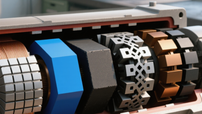
What Is a Magnet Engine and How Does It Work?

A magnet engine is a machine that uses magnetic fields to create or support mechanical motion. The idea often sounds simple: place permanent magnets around a rotor, add a stator, and expect continuous rotation. Reality is less generous. Magnets provide force, but they do not supply unlimited energy.

In a practical design, magnetic attraction and repulsion act through carefully shaped fields. A motor usually combines permanent magnets or electromagnets with coils, a rotor, bearings, and an electronic controller. When electric current changes direction in the coils, the magnetic field pushes the rotor forward. This produces torque, which can turn a fan, pump, or vehicle wheel. The battery or power supply remains essential.

The phrase “magnet engine” can describe several different devices, including permanent-magnet motors and experimental magnetic mechanisms. These systems are not automatically self-powering. A rotor may spin briefly after being released, but friction, air resistance, and magnetic equilibrium eventually reduce its motion. That detail is easy to overlook.

A reliable explanation should separate useful engineering from unsupported claims. Measurements matter. Engineers check input power, output torque, speed, heat, and electrical losses with calibrated instruments. Even simple bench testing can reveal disappointing results. That is valuable evidence, not failure.

This article explains how magnetic fields interact, how motor components cooperate, and why magnet-only energy claims usually conflict with established physics. It also considers efficiency, design limits, and safe testing practices. Understanding those limits makes the subject more practical, clearer, and far less mysterious.

What Is a Magnet Engine and How Does It Work?

Definition and Basic Concept of a Magnet Engine

What Is a Magnet Engine and How Does It Work?

Definition and Basic Concept of a Magnet Engine

A magnet engine is a mechanical system that uses magnetic forces to produce rotational movement. The term can be misleading. Magnets do not create unlimited energy. They provide force, while an external energy source usually maintains continuous motion. In practical designs, that source is commonly electrical power.

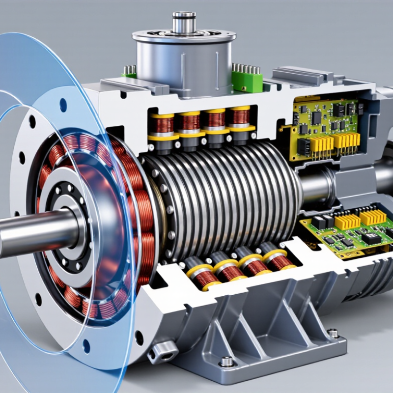
A basic magnet engine contains a rotor, a stationary section, and magnetic elements. Permanent magnets may sit on the rotor, while coils remain fixed around it. When current passes through a coil, it creates a magnetic field. The field attracts or repels the rotor magnets, producing torque. A controller then changes the current direction at carefully timed intervals. This keeps the rotor turning instead of stopping at one position.

The effect is easy to picture. Imagine small magnets moving past energized coils on a circular track. Each coil gives the rotor a short, controlled push. Not magic. Just timing and force. A useful test measures voltage, current, speed, and heat during operation. Friction, electrical resistance, and imperfect alignment reduce efficiency. Even a quiet motor loses energy through vibration and air movement. Some demonstrations appear self-running because they hide the power supply or overlook measurement errors. That is why careful testing matters. The design may still be valuable, but its performance must be judged by measured input and output, not motion alone.

Key Components and Magnetic Forces Involved

A magnet engine usually refers to a permanent-magnet motor, not a machine that creates free energy. Its rotor carries permanent magnets, while the stator contains copper windings around steel teeth. When controlled electric current enters the windings, it creates a rotating magnetic field. The rotor follows that field because opposite magnetic poles attract and similar poles repel. This interaction produces torque at the shaft.

The key components are the rotor, stator, magnets, windings, bearings, position sensors, and electronic controller. Neodymium-based magnets provide strong magnetic flux in a compact space, while ferrite magnets offer lower cost but usually less power density. The controller changes current direction at precise rotor positions. Small timing errors can create torque ripple, vibration, and audible noise. Not perfectly smooth.

Magnetic force depends on field strength, air-gap distance, pole shape, and current. A narrow, even air gap is valuable, but manufacturing tolerances make it difficult. Heat also weakens some magnets and increases copper resistance. The International Energy Agency reports that electric motor systems consume roughly half of global electricity, making efficiency improvements important. Its critical-minerals outlook also indicates that clean-energy demand for rare-earth elements could roughly triple by 2040 from 2020 levels. These figures explain the interest in efficient magnetic machines, but they do not prove that magnets alone supply energy. Practical testing still requires torque measurements, thermal imaging, vibration analysis, and efficiency mapping under changing loads. Theory can look cleaner than hardware.

Step-by-Step Operation of a Magnet Engine

A magnet engine usually describes a device that uses magnetic attraction and repulsion to create rotation. However, permanent magnets do not provide unlimited energy. They supply a force, not a continuous power source. This distinction matters when evaluating online demonstrations.

Step by step, the process begins with magnets arranged around a rotor and a fixed outer frame. The rotor magnet moves toward an oppositely positioned magnetic field. As it approaches, attraction produces torque and turns the shaft. The arrangement then changes through a switching mechanism, such as an electromagnetic coil or a carefully timed mechanical guide. This change prevents the rotor from stopping at its most stable position. The cycle repeats while an external energy source powers the switching system. In practical testing, friction, air resistance, electrical losses, and heat gradually reduce output. A rotor may spin smoothly, yet that does not prove it produces surplus energy. That is the common mistake.

Tips: Measure input and output separately. Use a tachometer, torque sensor, and reliable electrical meter. Record temperature and running time. Keep the setup shielded from nearby metal objects. Compare results under the same load. A simple test is better. If the measurements seem impressive, repeat them independently. Some designs look convincing but ignore hidden input power or starting energy. Careful testing may reveal flaws, and that is useful engineering progress.

Energy Conversion and Common Design Principles

What Is a Magnet Engine and How Does It Work?

Energy Conversion and Common Design Principles

A magnet engine uses magnetic fields to produce or control motion, but magnets do not create energy by themselves. They provide force through attraction and repulsion. An external source must supply the original mechanical or electrical energy. This distinction matters.

In a typical design, a rotor carries permanent magnets while a stationary stator contains copper coils. As the rotor turns, its magnetic field crosses the coils and changes the magnetic flux. Faraday’s law describes this process: changing flux induces voltage. Connecting the coils to a load allows electrical current to flow. In reverse, controlled current in the stator can create torque and drive the rotor.

Common designs use radial or axial magnetic paths. The air gap requires careful control. A smaller gap can improve magnetic coupling, yet it may increase manufacturing difficulty. Designers also consider coil shape, pole spacing, heat removal, and material strength. Poor alignment causes vibration and uneven torque. Friction, electrical resistance, and magnetic losses reduce useful output.

Testing should measure input power, output power, temperature, and rotational speed. A bright lamp alone proves little. It may hide unstable voltage or excessive heating. The term “magnet engine” can therefore be misleading. The system is an energy converter, not a self-running power source. Even well-built prototypes reveal compromises that calculations sometimes overlook.

Limitations, Efficiency, and Practical Applications

A magnet engine usually means a permanent-magnet motor. It does not create energy from magnets alone. Magnets supply a steady magnetic field, while electrical current creates a rotating field in the stator. The interaction produces torque on the rotor. An inverter adjusts current timing and speed. The rotor then turns a shaft for useful mechanical work.

Its limitations matter more than the label suggests. Copper resistance, bearing friction, switching losses, and heat reduce efficiency. A well-designed motor can exceed 90% efficiency, but performance changes sharply under partial load. The International Energy Agency’s Energy Efficiency 2023 report estimates that electric motor systems consume about 53% of global electricity. Small efficiency gains therefore have enormous consequences. Still, the figure is not universal. Real installations often suffer from poor sizing, dust, misalignment, or inadequate cooling.

Permanent magnets also create supply and temperature challenges. Excessive heat can weaken magnetic performance, while rare-earth materials may increase cost and sourcing risks. The IEA’s Global Critical Minerals Outlook 2024 reports that one country provides more than 90% of refined rare-earth supply. That concentration deserves careful engineering, not panic. Practical applications include electric vehicles, industrial pumps, robotics, compressors, and wind-turbine generators. In a workshop, the difference is visible: a cooler motor, quieter bearings, and lower electricity readings. Yet calling it an “engine” can mislead readers. It is an efficient electromechanical converter, not a perpetual-motion device.

What Is a Magnet Engine and How Does It Work? — Limitations, Efficiency, and Practical Applications
Data Dimension Key Fact or Typical Range How It Works or What It Means Practical Relevance
Definition A “magnet engine” commonly refers to a permanent-magnet motor, a magnetic demonstration device, or a claimed self-running magnetic machine. Permanent magnets create a magnetic field, but they do not provide an unlimited supply of mechanical energy. The term should be defined carefully before comparing performance or efficiency.
Energy Input Required for continuous operation A practical motor needs electrical, mechanical, or another external energy input to maintain continuous rotation and overcome losses. A device that only uses fixed magnets and claims sustained net power without an energy source conflicts with energy-conservation principles.
Main Operating Principle Interaction between magnetic fields Torque is produced when the magnetic field of the stator interacts with the magnetic field of the rotor. In most modern designs, electronic switching changes the stator field as the rotor turns. This principle is used in brushless DC motors, permanent-magnet synchronous motors, generators, pumps, fans, and robotic systems.
Permanent-Magnet Role Provides a fixed magnetic field The magnets replace or supplement an electrically energized rotor field. This can reduce rotor electrical losses and simplify some motor designs. Permanent magnets can improve power density and reduce maintenance, but they do not eliminate copper, iron, bearing, windage, or electronic losses.
Torque Production Depends on field strength, current, geometry, and control timing Useful torque is generated when the magnetic fields are deliberately positioned at an angle that produces rotation. Continuous torque requires repeated commutation or an alternating rotating field. Accurate control is essential for efficient starting, speed regulation, and operation under changing loads.
Typical Motor Efficiency Approximately 80%–97% for well-designed systems Efficiency varies with motor size, speed, load, winding resistance, magnetic material, cooling, bearings, and the associated controller. Efficiency is a measured ratio of useful mechanical output to supplied electrical input; it is never greater than 100% in a real system.
Peak Efficiency Conditions Usually near a designed speed and moderate-to-high load Motor losses may include copper loss, core loss, friction, windage, stray-load loss, and inverter loss. These losses change with speed and load. Operating far below or above the design point can substantially reduce efficiency and increase heating.
Starting Behavior Often requires electronic control or an auxiliary starting method A permanent-magnet synchronous motor is not inherently self-starting from a fixed-frequency supply because the rotor must synchronize with the rotating magnetic field. Controllers, position sensors, sensorless algorithms, or special winding arrangements are commonly used for reliable startup.
Speed Control Typically achieved by varying electrical frequency or commutation timing Electronic drives adjust current magnitude, phase, and frequency to control torque and speed. Variable-speed control can improve energy use in fans, pumps, conveyors, appliances, and electric traction systems.
Energy Density High compared with many electrically excited motor designs Permanent magnets can provide strong magnetic flux without continuous field current, allowing compact motor designs with reduced rotor excitation losses. High power density is useful where weight and size are important, such as mobile equipment and compact automation systems.
Thermal Limitations Magnetic performance decreases when magnets become too hot Every permanent-magnet material has a temperature limit. Excessive heat can reduce magnetic strength temporarily or cause irreversible demagnetization. Cooling, current limiting, thermal monitoring, and suitable material selection are required in demanding applications.
Demagnetization Risk Possible under excessive temperature, opposing fields, or mechanical damage Strong fault currents and unsuitable operating conditions can partially weaken the rotor magnets. Motor design must account for short-circuit conditions, overloads, vibration, impact, and long-term thermal exposure.
Mechanical Losses Increase with speed and imperfect alignment Bearings, seals, air resistance, imbalance, and friction convert part of the input energy into heat and noise. Precision manufacturing, lubrication, balancing, and appropriate operating speed help reduce these losses.
Electrical Losses Mainly winding resistance and power-electronic losses Current flowing through windings produces heat according to resistive losses. Inverters also consume energy through switching and conduction. Efficient windings, proper conductor sizing, optimized switching, and adequate cooling improve system performance.
Regenerative Operation Possible when the rotor is driven by an external mechanical source The motor can operate as a generator when mechanical energy forces the magnetic field to move relative to the windings. Electrical output comes from the mechanical input. Regeneration can recover energy during braking or descending loads, but conversion losses remain present.
Maintenance Profile Generally low for brushless designs Eliminating brushes and mechanical commutators reduces wear-related maintenance, although bearings, insulation, sensors, and electronics still require attention. Low maintenance is valuable in continuous-duty machinery and locations where servicing is difficult.
Control-System Requirement Often includes an inverter, controller, and protection functions The controller manages commutation, current, speed, position, startup, overload protection, and sometimes regenerative braking. The total system cost and complexity may be higher than the motor-only price suggests.
Practical Application: Fans and Pumps Efficient variable-speed airflow and fluid movement The controller adjusts motor speed to match demand, avoiding unnecessary throttling or constant full-speed operation. Potential benefits include lower energy consumption, quieter operation, and improved process control.
Practical Application: Electric Transportation High torque density and efficient speed control Permanent-magnet motors can provide strong low-speed torque and operate across a broad speed range with electronic control. They are suitable for traction, auxiliary drives, and compact mobility systems when thermal and cost requirements are satisfied.
Practical Application: Robotics Precise torque and position control Fast electronic feedback allows accurate movement, rapid response, and controlled holding torque. Common uses include robotic joints, servo mechanisms, automated tools, and positioning equipment.
Practical Application: Renewable-Energy Generators Mechanical rotation converted into electrical power Wind, water, or another prime mover turns the rotor, causing changing magnetic flux in the stator windings and inducing voltage. Permanent-magnet generators can operate without a separate rotor excitation supply, which may simplify some generator systems.
Material Considerations Magnet choice affects temperature capability, size, and cost Different permanent-magnet materials offer different combinations of magnetic strength, temperature tolerance, mechanical robustness, and supply considerations. Material selection should be based on the operating temperature, required flux, environmental conditions, and lifecycle requirements.
Environmental Considerations Material recovery and end-of-life handling may be important Magnets and motor assemblies can contain materials that require appropriate separation, recycling, or controlled disposal. Designs that support disassembly and material recovery can reduce environmental impact over the product lifecycle.
Core Limitation Magnets cannot create continuous net energy from nothing Magnetic forces can store, transfer, and redirect energy, but a cyclic device cannot deliver sustained output without an external energy source. Claims of perpetual motion should be tested with complete input-output measurements, including hidden electrical, mechanical, and thermal inputs.
Scroll to Top