Why Choose an IPM SynRM Motor for Industrial Applications?
Industrial plants rarely operate under ideal conditions. Pumps may run for long shifts, conveyors face changing loads, and limited cabinet space can complicate drive selection. An ipm synrm motor combines interior permanent magnets with synchronous reluctance torque, offering a practical option where efficiency and compact output matter. Its rotor design can reduce reliance on magnets compared with some permanent-magnet motors, though exact material use depends on the manufacturer and model. The distinction matters.
For engineers, the decision should start with real operating data: load profile, speed range, duty cycle, ambient temperature, and available inverter controls. An IPM SynRM can deliver efficient performance across suitable operating ranges, but results depend on motor sizing, drive settings, and installation quality. A nameplate rating alone is not enough. Check the full system.
This article examines where the technology fits, how it compares with other industrial motor types, and what to verify before specifying one. That includes efficiency maps, cooling needs, maintenance access, and supplier documentation. Small details count. A motor that performs well on a test bench may behave differently in a dusty plant or under frequent speed changes. No design is universally best, and published efficiency figures do not replace application-specific evaluation. A careful comparison can help plant teams balance energy use, control requirements, reliability, and purchase cost without assuming that one motor architecture solves every problem.
IPM SynRM Motor: Definition and Operating Principle
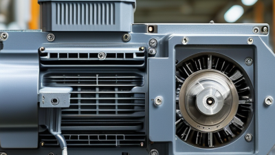
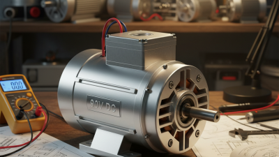
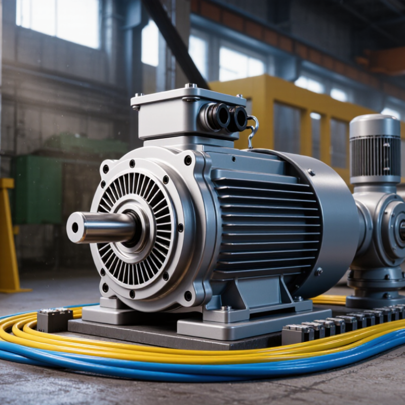
An IPM SynRM combines two sources of torque. Permanent magnets sit inside the rotor, while its iron paths are shaped to create magnetic reluctance differences. When stator windings receive controlled AC current, they produce a rotating magnetic field. The rotor follows that field at synchronous speed. Torque comes both from magnet interaction and from the rotor aligning with the field’s lower-reluctance path. An inverter adjusts current timing to control speed and torque.
In industrial service, this design can offer efficient operation across a useful speed range, especially when the drive is tuned for the actual load. A pump may run steadily, while a conveyor faces changing material weight. Those details matter. The motor is not automatically efficient in every installation; poor control settings, cooling limits, or frequent overloads can reduce its advantages. The label can sound simpler than the design really is.
Tips: Check the drive’s current settings and the motor’s thermal limits during commissioning. Record operating temperature under a typical load. Small adjustments can help, but results should be verified on site.
Key Components and Rotor Design
Why Choose an IPM SynRM Motor for Industrial Applications?
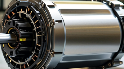
An IPM SynRM combines a wound stator with a rotor containing buried permanent magnets and shaped flux barriers. The stator’s rotating magnetic field drives the rotor, while magnet torque and reluctance torque contribute to rotation. The U.S. Department of Energy’s 2014 motor-systems sourcebook estimates that motor-driven systems use about 68% of electricity consumed in U.S. manufacturing. That figure highlights why efficient motor design matters, though actual savings depend on the machine and its duty cycle.
Rotor details matter. Laminated electrical-steel sheets limit eddy-current losses. Magnet pockets guide magnetic flux, while narrow steel bridges hold the rotor together at speed. Their shape affects torque, leakage flux, and mechanical strength. Small design changes can shift performance. The layout is not magic: poor drive tuning or a mismatched load can erode expected benefits. This is easy to overlook.
Tips: Match the motor to the real load and speed range. Check the inverter settings, cooling conditions, and rotor speed limits. Ask for test data across the operating range, not just a peak-efficiency figure. A quick comparison helps.
Efficiency, Torque, and Performance Advantages
An IPM SynRM combines interior permanent magnets with a rotor shaped to guide magnetic flux along preferred paths. This allows the motor to produce both magnet torque and reluctance torque. The result can be strong torque from a compact package, useful for pumps, compressors, conveyors, and machine tools. It can also maintain high efficiency across a range of operating points, not just at one fixed speed. That matters when production shifts between light and heavy loads.
Performance depends on the entire drive system. A compatible inverter and well-tuned control strategy help provide smooth starts, precise speed regulation, and responsive torque. A conveyor may hold speed as boxes arrive, while a pump adjusts output to match demand. Lower rotor losses can help limit heat, but cooling and operating conditions still matter. No motor type eliminates the need for correct sizing. A rushed selection can disappoint.
Tips: Compare efficiency maps at your actual speeds and loads. Check peak torque, overload duration, cooling needs, and inverter compatibility. Ask for measured data, not only a rated-efficiency figure. The trade-off is real: control can be more demanding than with a basic induction motor. Test the motor under your duty cycle before committing.
Industrial Applications and Operating Environments
IPM SynRM motors can suit industrial systems that need efficient, variable-speed operation. Their rotor combines embedded magnets with reluctance torque, supporting applications such as pumps, fans, compressors, and conveyors. In a water-treatment plant, for example, a pump may run below full speed for much of the day. Matching motor speed to demand can reduce wasted energy, though actual savings depend on the system and its controls. The details matter.
Operating conditions should guide selection. A dusty workshop, a hot compressor room, and a washdown area place different demands on the motor enclosure and cooling method. High ambient temperatures can reduce thermal margin, while vibration or poor alignment may shorten bearing life. Check the required torque across the full speed range, especially during startup or low-speed operation. Also confirm that the motor and inverter are correctly matched for the intended duty cycle. It is easy to focus on efficiency figures and overlook maintenance access or installation constraints. A careful site review helps establish whether this motor type fits the real operating environment, not just the specification sheet.
Selection Factors for Industrial Motor Systems
Selecting an IPM SynRM motor starts with the machine’s real duty cycle, not its peak rating. Record typical load, start frequency, speed range, and hours spent at partial load. An IPM-assisted synchronous reluctance rotor combines magnet torque with reluctance torque, which can support efficient operation across varied speeds. But the benefit depends on the application. A conveyor running steadily at moderate load has different needs from a pump with frequent speed changes.
Check the motor and drive as one system. Confirm that the inverter supports the required control method, operating range, and overload duration. Compare efficiency across expected load points, not only at full load. Review cooling, ambient temperature, enclosure protection, and available space; a dusty mill or hot pump room can change thermal performance. Also examine shaft fit, bearing loads, cable length, and commissioning support. These details matter.
Ask for test data under conditions close to your process. A catalog figure alone may not predict energy use on site. That boundary is easy to miss. If the load profile is uncertain, measure it before sizing the motor. Real installations rarely behave exactly as a spreadsheet suggests. Some estimates will be imperfect, so leave room to validate settings during commissioning.