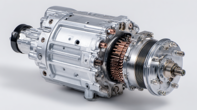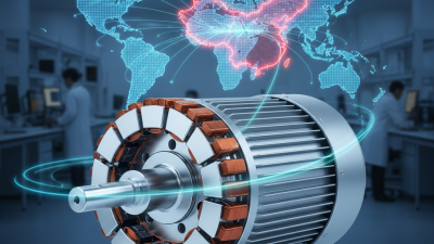
Electric vehicle demand is moving from early adoption toward mainstream transport. The International Energy Agency’s Global EV Outlook 2024 reported nearly 14 million electric car sales in 2023, representing about 18% of global car sales. This rapid growth is increasing pressure on manufacturers to deliver longer range, faster acceleration, quieter operation, and lower energy consumption. In this environment, the pmsm motor for electric vehicles has become a widely studied traction solution.
PMSM technology combines permanent magnets with a rotating magnetic field. This design can provide high torque density, strong efficiency, and compact packaging. Those benefits matter inside a modern vehicle, where every kilogram affects range. The U.S. Department of Energy’s Vehicle Technologies Office identifies permanent-magnet traction motors as important because they can deliver high power density and efficient operation across demanding drive cycles. A smaller motor may also create more room for batteries, cooling hardware, or passenger comfort.
The advantages are not absolute. Rare-earth magnet supply, material costs, thermal management, and recycling remain practical concerns. The International Energy Agency has repeatedly highlighted supply-chain concentration for critical minerals, including rare earth elements used in permanent magnets. Engineers must examine the full duty cycle, not only peak efficiency on a test bench. A motor that performs brilliantly during acceleration may need careful cooling on a steep road. That distinction is easy to miss. For buyers and manufacturers, choosing a PMSM motor means balancing efficiency, packaging, durability, cost, and supply resilience rather than chasing one impressive specification.
A permanent magnet synchronous motor, or PMSM, uses permanent magnets in its rotor and windings in its stator. The magnets create a steady magnetic field without consuming rotor-side electrical power. When three-phase current enters the stator windings, it produces a rotating magnetic field. The rotor follows this field and turns at the same electrical speed. That synchronized movement gives the motor its name.
In an electric vehicle, an inverter controls the current’s timing and strength. This control adjusts torque during starts, hills, and rapid acceleration. PMSM motors can deliver strong torque from low speed, while their compact design supports efficient packaging.
They also operate quietly, which drivers notice in city traffic. During testing, engineers monitor temperature, vibration, and efficiency across changing road loads. Small errors in sensor calibration can affect smoothness. That detail is easy to underestimate.
The magnets reduce some electrical losses, but they also create engineering challenges. Heat can weaken magnetic performance, and the motor may need careful cooling. Manufacturing tolerances matter too. A slight rotor imbalance can cause noise or vibration at high speed.
PMSM technology is not automatically the best choice for every vehicle. Engineers must compare cost, cooling needs, control complexity, and expected driving conditions. The practical answer depends on the whole powertrain, not the motor alone.
Why Choose a PMSM Motor for Electric Vehicles?
A permanent magnet synchronous motor converts battery electricity into vehicle motion through controlled magnetic fields. The battery sends direct current to an inverter. The inverter changes it into precisely timed alternating current. This current energizes copper windings around the stator. Their rotating magnetic field pulls the permanent-magnet rotor around. The rotor turns the shaft, gearbox, and wheels. Motion begins smoothly.
The inverter constantly adjusts frequency and current according to accelerator input, vehicle speed, and road resistance. More current usually creates more torque. Higher electrical frequency makes the rotor spin faster. During braking, the process reverses. The rotating wheels drive the motor, which produces electricity and returns some energy to the battery. Technicians often check temperature, vibration, and current response during testing. Small control errors can feel like hesitation. The conversion is efficient, but never perfect. Heat, electrical resistance, and mechanical friction still consume energy.
Tips: Keep cooling paths clean, because excessive heat can weaken performance and damage insulation. Use accurate sensors and calibrated control software. Real driving conditions matter more than laboratory numbers. A PMSM can deliver strong efficiency and quiet operation, yet it may face demagnetization risks under severe heat. Engineers must balance torque, cooling, battery range, and long-term reliability. The ideal design is rarely the simplest one.
How PMSM motors convert electrical energy into vehicle motion
This representative energy-flow profile starts with 100 kWh of electrical energy. The inverter converts battery DC power into AC power, while the PMSM uses a rotating magnetic field and permanent magnets to produce shaft torque. After motor and drivetrain losses, approximately 89 kWh reaches the wheels. Actual efficiency varies with speed, load, temperature, and control strategy.
Why Choose a PMSM Motor for Electric Vehicles?
Key Advantages of PMSM Motors in Electric Vehicles
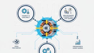
Permanent magnet synchronous motors offer strong performance in a compact package. Their permanent magnets create a steady magnetic field without continuous rotor current. This reduces electrical losses and supports high efficiency during daily driving. In practical EV testing, that efficiency can improve range and reduce battery heat. The motor also delivers high torque from a standstill. That makes launches smooth, quick, and predictable.
PMSM motors respond rapidly to changes in accelerator input. Their precise control helps vehicles manage torque on hills, wet roads, and tight corners. Regenerative braking can also feel more natural with accurate motor control. The system sends kinetic energy back to the battery during deceleration. Less energy becomes waste heat. Cabin noise may decrease too, because the motor runs smoothly with fewer mechanical vibrations.
PMSM designs are not flawless. They usually need sophisticated inverters, sensors, and control software. Permanent magnets can also face performance losses under excessive heat. Engineers must manage cooling carefully around the rotor and stator. Magnet materials may increase manufacturing costs and supply concerns. This trade-off deserves attention. In some vehicles, a different motor may better suit the budget or duty cycle. Real-world performance depends on calibration, thermal design, battery voltage, and driving conditions. A well-designed PMSM system still gives electric vehicles an impressive balance of efficiency, response, and packaging flexibility.
Permanent magnet synchronous motors (PMSMs) remain central to modern electric vehicle design. The International Energy Agency reported nearly 14 million electric cars sold worldwide in 2023. That scale increases pressure on motor efficiency, thermal control, and material use.
PMSMs generally fall into two main types: surface-mounted and interior permanent magnet motors. Surface-mounted designs place magnets on the rotor surface. They offer simple construction and strong efficiency at moderate speeds. Interior permanent magnet motors embed magnets inside the rotor. This layout supports higher-speed operation and adds reluctance torque, improving performance during acceleration. Passenger cars often favor interior designs because compact packaging matters. Surface-mounted motors can suit lighter vehicles and selected hybrid systems.
The choice changes with the vehicle duty cycle. Electric buses and delivery vans need steady torque, repeated starts, and dependable cooling. Larger commercial vehicles may require reinforced rotors and wider operating maps. The U.S. Department of Energy identifies motor efficiency, power density, and thermal management as major electric-drive priorities. Rare-earth magnet supply also deserves attention. PMSMs are efficient, but they are not automatically the best solution for every platform. Induction motors or electrically excited machines may reduce material concerns, although they can bring higher losses or greater system complexity. That trade-off is real. Engineers should validate it through road-load data, temperature testing, and fleet duty cycles, not brochure figures.
| PMSM Type | Rotor Magnet Arrangement | Key Operating Characteristics | Typical EV-Relevant Speed Range | Main Advantages | Main Limitations | Common Vehicle Applications |
|---|---|---|---|---|---|---|
| Surface-Mounted PMSM (SPMSM) | Permanent magnets mounted on the outer surface of a cylindrical rotor. | Torque is produced mainly by the interaction between the rotor magnets and the stator magnetic field. Rotor saliency is low, so reluctance torque is limited. | Approximately 3,000–10,000 rpm, depending on rotor retention, materials, and cooling design. | Simple rotor construction; low torque ripple when properly designed; high efficiency at moderate speed; good controllability. | Surface magnets require strong mechanical retention; high-speed field weakening is generally more challenging than with interior-magnet designs. | Compact passenger-car traction motors, electric scooters, light-duty vehicles, and auxiliary electric drives. |
| Interior PMSM (IPMSM) | Permanent magnets embedded inside the rotor, commonly in radial, V-shaped, or multi-layer configurations. | Combines magnet torque with reluctance torque. The rotor has saliency, enabling a broad constant-power operating region through field weakening. | Approximately 4,000–18,000 rpm in traction systems; the actual limit depends on rotor stress and mechanical design. | High power density; strong low-speed torque; good high-speed capability; efficient regenerative braking; magnets are mechanically protected by the rotor core. | More complex rotor manufacturing; greater sensitivity to magnet placement and demagnetization analysis; requires advanced control and manufacturing tolerances. | Main traction motor for battery-electric passenger cars, plug-in hybrid vehicles, electric SUVs, and performance-oriented electric drivetrains. |
| V-Shaped IPMSM | Two or more magnet pieces are positioned in a V-shaped cavity inside each rotor pole. | The V geometry creates useful saliency and directs magnetic flux toward the air gap, supporting both magnet torque and reluctance torque. | Approximately 5,000–16,000 rpm in many passenger-vehicle traction designs. | High torque density; favorable efficiency over a wide load range; good field-weakening performance; strong balance between launch torque and high-speed operation. | Rotor geometry is more difficult to manufacture; bridges and flux barriers must be designed carefully to control stress and leakage flux. | Passenger-car traction units requiring high efficiency, compact packaging, and a wide operating speed range. |
| Spoke-Type IPMSM | Magnets are placed radially or tangentially inside the rotor, resembling spokes around the shaft. | Produces high air-gap flux and significant reluctance torque. The configuration can achieve high torque per unit volume at relatively low speed. | Approximately 2,000–10,000 rpm, with the upper limit determined by rotor strength and retention features. | High torque density; suitable for high-load starts; effective use of magnetic flux; can support compact motor packaging. | Higher risk of leakage flux and torque ripple; rotor bridges and mechanical supports require careful optimization. | Electric buses, commercial vehicles, heavy-duty traction, and applications prioritizing high starting torque. |
| Multi-Layer IPMSM | Multiple layers of embedded magnets and flux barriers are arranged within each rotor pole. | Magnetic paths are optimized to increase saliency, reduce leakage flux, and shape the torque waveform across a wide speed range. | Approximately 5,000–20,000 rpm in advanced traction designs, subject to rotor-stress and inverter limits. | Very high power density; broad constant-power range; high efficiency potential; reduced torque ripple when optimized with suitable control. | Complex manufacturing, higher design and validation cost, and demanding requirements for rotor strength and dimensional accuracy. | High-performance passenger vehicles, high-speed electric axles, and applications with strict mass and packaging limits. |
| Axial-Flux PMSM | Magnets are arranged on one or more disc-shaped rotors, with magnetic flux traveling predominantly in the axial direction. | Short axial length and a large effective torque radius can provide high torque density, especially in flat motor packages. | Often approximately 2,000–8,000 rpm in vehicle-oriented designs; speed capability varies significantly by rotor structure. | Very compact axial packaging; high torque density potential; suitable for integrating the motor into wheels, transmissions, or hybrid powertrains. | More demanding thermal management, air-gap control, bearing loading, manufacturing, and structural design than many radial-flux motors. | Specialized electric vehicles, compact urban vehicles, high-performance drivetrains, and hybrid powertrain modules where axial space is limited. |
| Dual-Rotor or Dual-Stator PMSM | Uses two active air gaps, such as one rotor between two stators or two rotors surrounding a stator, depending on the architecture. | Increases active electromagnetic surface area and can improve torque production within a short axial package. | Typically approximately 2,000–10,000 rpm in vehicle applications, depending on the selected topology and mechanical constraints. | High torque density; potentially improved utilization of stator copper and active material; flexible packaging options. | More complicated assembly, cooling channels, alignment, inverter integration, and maintenance requirements. | High-torque electric axles, specialized commercial vehicles, multi-motor systems, and applications requiring compact high-output propulsion. |
A permanent magnet synchronous motor (PMSM) offers high torque density and efficient operation, making it attractive for electric vehicles. Yet its permanent magnets create design constraints that engineers cannot treat as minor details. Neodymium-based magnets can lose performance when exposed to excessive heat. The risk rises near the rotor during sustained high-speed driving. Cooling must reach the right components, not merely the outer housing. In practical testing, a temperature sensor in the wrong location can produce reassuring but incomplete data.
PMSM control also demands a precise inverter and rotor-position estimate. Back electromotive force increases with speed, so field weakening becomes necessary above the base-speed region. This control consumes voltage headroom and may reduce efficiency. Poor calibration can cause torque ripple, acoustic noise, or harsh regenerative braking. Cogging torque remains another concern at low speed. It can make launch feel uneven, especially when the drivetrain has little mechanical damping. Small errors become noticeable.
Material cost and supply stability deserve equal attention. High-performance magnets can raise manufacturing expense and complicate recycling. Magnet retention, rotor balance, insulation, and bearing temperatures require validation across cold starts, steep climbs, and repeated acceleration. Engineers should also define safe behavior after sensor faults or inverter failures. A motor that performs well on a dynamometer may behave differently in traffic. That gap is where many design assumptions need revisiting. Margins disappear.