What Is a 3 Phase Permanent Magnet Motor?

A 3 phase permanent magnet motor converts electrical power into mechanical motion through three-phase windings and a permanent-magnet rotor. Unlike induction motors, it does not need rotor current to create its magnetic field. That difference can reduce electrical losses, improve torque density, and support compact equipment designs. The result is visible in practice: a smaller motor can drive a conveyor, pump, compressor, or electric vehicle with less wasted heat.

Industry data supports this growing interest. The U.S. Department of Energy reports that motor-driven equipment represents a major share of industrial electricity consumption, making efficiency improvements financially significant. The International Energy Agency also identifies electric motors as essential to transport, buildings, and manufacturing. These reports do not make permanent-magnet technology universally superior. Rare-earth material costs, demagnetization risks, thermal limits, and inverter complexity still require careful engineering.

Professor Jacek F. Gieras, a recognized authority on permanent-magnet machines, states: “Permanent magnet machines have many advantages over conventional electrical machines.” That observation remains useful, but it needs context. Efficiency depends on operating speed, cooling, control software, load patterns, and manufacturing quality. A laboratory rating may look impressive. Real factory conditions can be less forgiving. Understanding those trade-offs is the purpose of this guide, which examines how a 3 phase permanent magnet motor works, where it performs best, and why engineers sometimes choose another motor design.
What Is a 3 Phase Permanent Magnet Motor?

Definition: How a Three-Phase PM Motor Produces Synchronous Torque

What Is a 3 Phase Permanent Magnet Motor?

Definition: How a Three-Phase PM Motor Produces Synchronous Torque

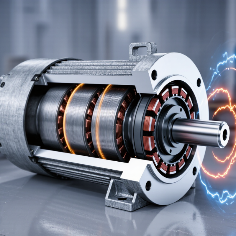
A three-phase permanent magnet motor uses three stator windings spaced 120 electrical degrees apart. An inverter supplies three-phase currents, creating a rotating magnetic field inside the stator. Permanent magnets on the rotor follow this field and produce synchronous torque. The rotor does not normally slip behind the rotating field. Its speed is defined by the electrical frequency and pole count: synchronous speed equals 120 times frequency divided by pole pairs.

The torque comes from magnetic alignment. When the rotor magnets try to align with the stator field, tangential force turns the shaft. Interior-magnet designs can add reluctance torque through rotor saliency, improving output in some operating regions. In commissioning work, engineers check phase order, encoder position, current angle, and thermal limits. A small position error can create vibration, noise, or weak starting torque. The ideal diagram is tidy. Factory current is not.

The International Energy Agency’s energy-efficiency analyses report that motor-driven systems consume roughly half of global electricity. This makes controllable motor efficiency commercially important, not merely theoretical. The European Commission’s ecodesign assessments also identify motors and drives as major electricity-saving opportunities. Efficiency depends on the full system, including the inverter, bearings, cooling, and load profile. A permanent magnet motor can be highly efficient, but it is not automatically efficient in every application. That distinction deserves more attention.

Electrical Structure: Three Windings Spaced 120° Apart and Inverter Commutation

A three-phase permanent magnet motor uses three stator windings positioned 120 electrical degrees apart. Each winding creates a magnetic field when energized. A permanent-magnet rotor follows the rotating field, producing torque with little rotor loss. The arrangement resembles three carefully timed pushes around a circle.

The inverter controls this timing. It converts direct-current input into three changing phase currents, then commutates them according to rotor position. Hall sensors, encoders, or sensorless estimation can provide that position. In practice, phase current must match rotor angle closely. A small timing error can increase torque ripple, heat, and audible noise.

The IEA’s Energy Efficiency 2023 report estimates that electric motor systems consume roughly half of global electricity. The U.S. Department of Energy’s Motor Systems Market Assessment also reports that motor systems use about 57% of electricity in American manufacturing. These figures explain why inverter control matters beyond laboratory performance. A well-tuned inverter can adjust frequency and current instead of forcing the motor to run at one fixed speed.

Field testing often reveals details that simplified diagrams miss. Dead time, winding resistance, magnetic saturation, and sensor offset all affect commutation. The ideal 120-degree spacing is electrical, not always mechanical. That distinction causes confusion.

It is tempting to call permanent magnets automatically efficient. That is incomplete. Poor control can waste the advantage, especially during rapid acceleration or light-load operation. Engineers should check phase balance, temperature rise, current waveforms, and rotor alignment under real load conditions. Testing should continue after installation.

Rotor Engineering: NdFeB Magnets, Pole Count, and Flux-Linkage Design

What Is a 3 Phase Permanent Magnet Motor?

Rotor engineering strongly influences a three-phase permanent magnet motor’s torque, efficiency, and operating range. NdFeB magnets deliver high magnetic energy density, allowing a compact rotor with strong air-gap flux. According to the USGS Mineral Commodity Summaries 2024, global rare-earth mine production reached approximately 350,000 metric tons in 2023. The International Energy Agency reported more than 14 million electric vehicles sold globally in 2023, increasing pressure on magnet supply and material efficiency. This pressure matters.

Magnet selection must balance residual flux, coercivity, cost, and temperature resistance. At elevated rotor temperatures, irreversible demagnetization can reduce torque permanently. Thermal margin is easy to underestimate. Pole count also changes the design compromise. More poles can improve torque density and shorten end windings, but they increase electrical frequency and iron loss. Fewer poles may simplify high-speed operation, although they can require larger magnets or higher current. A rotor that looks efficient in simulation may perform differently after heat cycling.

Flux linkage connects magnet strength with winding performance. In simplified form, permanent-magnet flux linkage equals turns multiplied by air-gap flux. It directly affects back electromotive force and voltage limits. Engineers usually verify this relationship through finite-element analysis, open-circuit back-EMF testing, and temperature measurements. Small alignment errors between magnet segments can disturb the waveform. That detail is often overlooked. NdFeB grades, pole arcs, bridge thickness, and rotor skew should therefore be evaluated together, not separately.

Speed and Efficiency: Using n = 120f/p and IE4–IE5 Performance Classes

What Is a 3 Phase Permanent Magnet Motor?

A 3 phase permanent magnet motor uses three AC phases and magnets embedded in, or attached to, its rotor. The stator creates a rotating magnetic field. The rotor follows this field with almost no slip during normal operation. Its synchronous speed is calculated with n = 120f/p, where n is speed in revolutions per minute, f is frequency in hertz, and p is the number of poles. For example, a four-pole motor supplied at 50 Hz reaches about 1,500 rpm. A variable-frequency drive can change frequency and control speed smoothly. In practice, cable losses, heat, and load changes still affect performance.

IE4 and IE5 describe high motor efficiency classes under applicable testing standards. IE5 generally demands less energy loss than IE4, but the label alone does not guarantee lower system consumption. Drive efficiency, partial-load operation, cooling fans, and gearbox losses also matter. A motor running at 30% load may perform differently from its published rating. Real installations are less tidy. I would verify test conditions, rated speed, duty cycle, and temperature before comparing quotations. Some specifications also use different measurement methods, which can create unfair comparisons.

Tips: Check the pole count before using n = 120f/p. Measure input power at the actual operating load. Keep the motor clean and adequately cooled. Small maintenance errors can erase expected IE4–IE5 savings.

Three-Phase Permanent Magnet Motor: Speed and Efficiency

The theoretical synchronous speed is calculated with n = 120f / p, where f is frequency in hertz and p is the number of poles. The chart shows calculated speed for a four-pole permanent magnet motor. Actual operating speed may be slightly lower under load, while IE4–IE5 efficiency performance depends on motor rating and operating conditions.

Application Selection: Power Rating, IP Protection, Cooling, and Thermal Limits

What Is a 3 Phase Permanent Magnet Motor?

A 3 phase permanent magnet motor uses a rotating magnetic field and permanent magnets on its rotor. It delivers high efficiency, steady torque, and precise speed control. Application selection requires more than matching the motor’s rated power. Check the real load profile, starting torque, acceleration time, and daily operating hours. A motor rated at 10 kW may overheat when the machine repeatedly peaks above that level. This is often missed.

Tips: Select power with measured load data, not guesswork. Confirm the service duty and ambient temperature. For dusty or wet areas, review the IP rating under IEC 60034-5. IP55 resists dust and water jets, but it is not fully waterproof. Cable glands and mounting positions also affect protection.

Cooling strongly influences thermal limits. A fan-cooled motor may lose capacity when airflow falls below its design value. A water-cooled unit needs clean flow, controlled temperature, and leak monitoring. Check the cooling method against the installation space and maintenance plan. Insulation class, winding temperature, bearing temperature, and magnet limits should appear in the technical documentation. Variable-speed operation can reduce cooling at low speed, even when torque remains high. I have seen selections fail here. The nameplate looked suitable, but the actual duty cycle was harsher. Leave a practical thermal margin, then verify it through testing or temperature data.

What Is a 3 Phase Permanent Magnet Motor? - Application Selection: Power Rating, IP Protection, Cooling, and Thermal Limits

Application Typical Power Range Typical Supply Typical Speed Range Recommended IP Rating Preferred Cooling Method Thermal Considerations Selection Notes
Conveyor Systems 2.2–30 kW 380–480 V, 3-phase, 50/60 Hz 750–1,800 rpm IP55 minimum; IP65 for dusty or washdown areas Totally enclosed fan-cooled, IC411; separately ventilated, IC416, for low-speed operation Allow for frequent starts, acceleration torque, and reduced airflow at low speed Size from the highest belt load and starting duty, not only average running power
Pumps and Fans 5.5–250 kW 380–690 V, 3-phase, 50/60 Hz 900–3,600 rpm IP55 for indoor service; IP56 or IP65 for exposed installations IC411 for constant-speed duty; IC416 or liquid cooling for high power density Variable-speed operation can reduce self-cooling; check minimum speed and continuous torque limits Use the pump or fan duty point, efficiency, speed, and system pressure or flow requirements
HVAC and Chiller Compressors 15–400 kW 380–690 V, 3-phase, 50/60 Hz 1,500–3,600 rpm IP55 minimum; higher protection where condensation is likely IC411 or IC416, depending on enclosure size and speed-control range Evaluate ambient temperature, refrigerant environment, overload duration, and hot-spot temperature Confirm compatibility with the inverter, compressor map, and required variable-speed operating envelope
Machine Tools 5–150 kW 380–480 V, 3-phase, variable frequency 1,500–12,000 rpm IP54–IP65, depending on chips, coolant, and enclosure design Forced-air or liquid cooling for compact, high-speed spindle designs Short-time overloads, high acceleration, bearing losses, and rotor temperature must be assessed Select by torque-speed curve, peak torque, speed accuracy, runout, and allowable duty cycle
Electric Vehicle Traction 20–250 kW continuous; higher peak ratings possible 300–800 V DC-link with an inverter 0–18,000 rpm, application dependent IP67 or higher for exposed vehicle locations Water-glycol jacket or oil cooling for high continuous torque density Limit stator winding, magnets, bearings, and inverter temperatures during repeated peak loads Use drive-cycle data rather than peak power alone; include regenerative braking and thermal soak
Industrial Robotics 0.4–30 kW 200–480 V, 3-phase, inverter driven 500–6,000 rpm IP54–IP65, based on dust, oil, and washdown exposure Natural or forced air for moderate duty; liquid cooling for compact joints Repeated acceleration and deceleration can create high RMS current and localized heating Check reflected inertia, peak torque, feedback requirements, and cable-flexing conditions
Material Handling and Hoists 3–160 kW 380–690 V, 3-phase, 50/60 Hz 300–1,800 rpm IP55 minimum; IP66 for outdoor or severe-duty service IC411 or IC416; external cooling is preferred for low-speed high-torque duty Consider duty class, braking cycles, shock loads, holding torque, and thermal recovery time Verify peak torque and braking energy independently from the continuous motor rating
Food, Beverage, and Washdown Equipment 0.75–45 kW 200–480 V, 3-phase, 50/60 Hz 750–3,600 rpm IP66–IP69, according to washdown pressure and temperature Totally enclosed fan-cooled or hygienic liquid-cooled designs Account for elevated ambient temperature, frequent cleaning cycles, and reduced external airflow Use corrosion-resistant construction and ensure the cable glands and connectors match the enclosure rating
General selection reference: A three-phase permanent magnet motor is normally operated through an inverter, which controls voltage, frequency, torque, and speed. Common industrial motors use insulation Class F with a 155°C maximum insulation-system temperature, while the permissible temperature rise depends on the design, ambient temperature, altitude, duty cycle, and applicable standard. IP ratings describe protection against solid objects and water ingress; they do not replace correct sealing, cable-gland selection, or maintenance practices.
Important: The ranges shown are general engineering guides. Final motor selection should be verified against the required torque-speed curve, duty cycle, inverter compatibility, ambient conditions, altitude, installation orientation, overload profile, and applicable IEC or equivalent standards.
Scroll to Top