How to Choose the Best Halbach Array Motor in 2026?
Choosing the best halbach array motor in 2026 is not simply a matter of selecting the highest torque rating. The right motor must match the machine, operating cycle, available space, and control system. A compact robot joint, for example, has different needs from a high-speed spindle. Start with the load profile: note peak and continuous torque, speed range, acceleration, and duty cycle. Small details matter. A motor that performs well on a specification sheet may run hot or inefficiently in the actual assembly.
Compare more than headline performance. Review motor dimensions, rotor inertia, cooling method, bearing arrangement, and compatibility with the drive. Ask how efficiency and temperature were measured, and under what conditions. Check the required sensors, wiring, and mounting tolerances, too. Real test data helps. If a supplier cannot explain its test setup, treat the numbers cautiously. That does not automatically make the product unsuitable, but it leaves an important question unanswered.
This guide examines the practical criteria behind a sound choice, from application requirements and technical specifications to supplier support and lifetime cost. It also considers trade-offs: higher torque density may bring tighter thermal limits, while a custom design can add lead time and integration work. There is no universal winner. The best option is the one that meets verified requirements with sensible margins, reliable documentation, and support you can actually use. Some comparisons remain imperfect; real-world testing should settle the close calls.
Understanding How a Halbach Array Motor Works
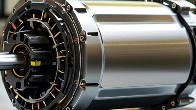
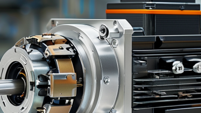
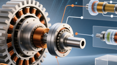
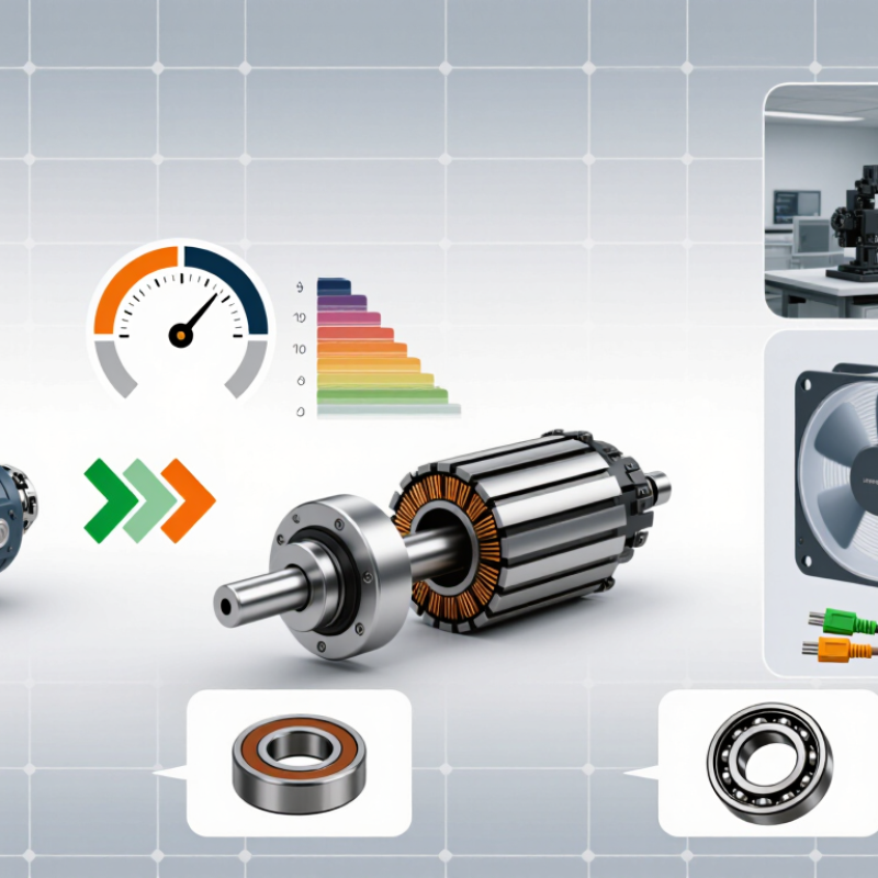
A Halbach array motor uses permanent magnets arranged so their magnetic fields reinforce on one side and partly cancel on the other. In a typical rotor, each magnet’s orientation turns slightly from its neighbor, creating a repeating pattern around the circumference. This concentrates useful flux toward the stator, where copper coils sit across a narrow air gap. That matters. When the controller sends timed current through the coils, their changing magnetic field interacts with the rotor’s field and produces rotation. The sequence of coil currents keeps the rotor moving. Not magic.
The concentrated field can support strong torque in a compact motor, but the result depends on the whole design. Magnet spacing, pole count, air-gap size, and coil geometry all affect performance. A small increase in the air gap can weaken magnetic coupling; heat can also reduce magnet strength and strain insulation. On a workbench, the arrangement may look simple. Building it accurately is less simple. For a 2026 motor choice, check the torque and speed range under real operating conditions, along with cooling, efficiency, and control requirements. Ask whether the supplier provides measured curves and temperature limits, not just peak figures. A Halbach array does not automatically make a motor quieter, smaller, or more efficient. Those benefits vary, and the trade-offs deserve a closer look.
How to Choose the Best Halbach Array Motor in 2026?
Understanding how it works: In an idealized linear Halbach array, the magnetization direction rotates along the array. These normalized curves show its horizontal and vertical components over one spatial wavelength.
The rotating magnetization pattern concentrates magnetic flux on one side of the array and weakens it on the other. When comparing motors, also consider air gap, array segmentation, cooling, speed, and torque requirements; this idealized pattern is not a measured motor-performance curve.
Defining Application and Performance Requirements
Define the motor by its real job, not by peak torque alone. A packaging-axis drive may need fast acceleration and frequent reversals; a pump may run steadily for hours. Record the load’s speed range, inertia, duty cycle, available voltage, cooling method, and mounting limits. IEA’s Global EV Outlook 2024 reports nearly 14 million electric-car sales in 2023, about 18% of new car sales. This is not Halbach-motor market data, but it illustrates why application-specific efficiency and thermal requirements matter. That distinction is easy to overlook.
For a Halbach array motor, compare continuous and peak torque across the full speed range. Check winding temperature, back-EMF against the inverter’s voltage limit, air-gap tolerance, and magnet operating temperature. A compact rotor may suit a tight installation, but packaging alone cannot establish performance. Ask for measured torque-speed and thermal results under a duty cycle close to yours. A neat spreadsheet can still miss a hot enclosure or a sharp load spike.
Tips: Write down the worst-case operating point before comparing designs. Include the actual acceleration time, ambient temperature, and cooling airflow. If the requirement is uncertain, measure it on the machine. Even a short test can reveal a mismatch between the calculated load and the real one.
Comparing Magnet Layouts, Motor Types, and Materials
A Halbach array concentrates magnetic flux toward one side, but the layout affects more than peak strength. A continuous ring can reduce gaps between poles, while segmented magnets are often easier to manufacture and replace. Segment angle and placement matter: small errors can weaken the intended field pattern. Check the air gap, too. A few millimeters can change force and efficiency noticeably. Small details matter.
Motor type should match the machine’s geometry and duty cycle. Radial-flux motors suit familiar cylindrical designs; axial-flux motors can deliver strong torque in a flatter package. Linear motors use a straight array and need careful control of end effects. Compare torque across the required speed range, not just the headline peak value. Cooling, bearing loads, and available installation space may outweigh a compact magnetic design. A neat simulation can still mislead if it omits heat or manufacturing tolerances.
Material choice brings its own trade-offs. Neodymium magnets offer high magnetic strength, but temperature limits and corrosion protection need attention. Samarium-cobalt generally tolerates higher temperatures, though it costs more and can be brittle. Ferrite is less powerful, yet may suit lower-cost, less demanding applications. Ask for temperature ratings, coating details, and measured field data. Then test a prototype under real load; the “best” layout on paper may not be best in service. That trade-off hurts.
Evaluating Efficiency, Thermal Limits, and Manufacturing Needs
A Halbach array can direct more magnetic flux toward the working air gap, but that does not guarantee a cooler or more efficient motor. Match the design to its real duty cycle: repeated starts, low-speed torque, and time spent near peak load. The IEA’s 2011 report, Energy-Efficiency Policy Opportunities for Electric Motor-Driven Systems, estimates that motor-driven systems use about 45% of global electricity. Small efficiency gains matter. Still, a peak-efficiency figure alone can mislead; compare performance across the speeds and loads your equipment actually uses.
Thermal limits need equal attention. Check winding temperature, cooling airflow, magnet temperature limits, and the adhesive used to hold segmented magnets. IEC 60034-1 defines thermal classes for rotating electrical machines, but the motor’s weakest component may set the practical limit. A tightly packed motor can look excellent on paper and struggle inside a dusty enclosure. Heat matters. Leave margin for ambient temperature and imperfect cooling, not just laboratory conditions.
Manufacturing needs can change the choice. Halbach arrays require precise magnet orientation and consistent air gaps; small placement errors can affect vibration and torque ripple. Ask suppliers how they inspect magnetization direction, control assembly tolerances, and verify each rotor. Compare the cost of complex magnet segmentation with the performance gain at your required production volume. One trade-off is easy to underestimate: the most efficient prototype may be harder to build repeatably. A simpler array may be the more dependable production choice.
Selecting and Verifying a Motor for 2026 Applications
How to Choose the Best Halbach Array Motor in 2026?
Selecting and Verifying a Motor for 2026 Applications
A Halbach array concentrates magnetic flux on one side of its magnet arrangement, but that alone does not guarantee better performance. Match the motor’s continuous and peak torque to the real load, including acceleration and duty cycle. Check the required speed, supply voltage, controller limits, and available space. Air-gap size matters; even a small change can affect force and efficiency. Small details matter. Ask for test conditions behind published figures, since results can vary with temperature and mounting.
Tips: Write down your load, speed range, and operating hours before comparing motors. Request winding resistance, back-EMF, and thermal limits. Measure, don’t guess.
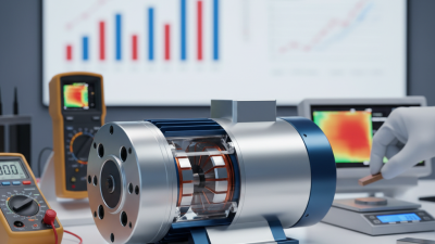
Verify the candidate under representative conditions. Use a torque sensor and speed measurement, then record current and winding temperature through a full-duty test. Check vibration and torque ripple at low and high speeds. Confirm that the controller handles the motor’s electrical characteristics without excessive current or heat. A spreadsheet can miss a loose mount or uneven cooling; I would not treat one clean test as proof. Repeat key measurements after warm-up, and document the setup so another engineer can reproduce them.