Electric motors rarely make headlines, yet they turn pumps, compressors, and production lines every day. The U.S. Department of Energy’s 2023 Improving Motor and Drive System Performance sourcebook estimates that motor systems use about 54% of electricity consumed by U.S. manufacturing. That figure makes motor design more than a technical detail. It affects energy bills, equipment sizing, and heat inside a factory cabinet. The International Energy Agency’s Energy-Efficiency Policy Opportunities for Electric Motor-Driven Systems also highlights the broad efficiency potential of motor and drive systems. But efficiency depends on the whole installation, not just the motor nameplate.
An ipm synrm motor combines interior permanent magnets with the flux-barrier rotor geometry of a synchronous reluctance motor. In operation, an inverter supplies controlled current to the stator windings, creating a rotating magnetic field. The rotor follows that field. Its embedded magnets provide permanent-magnet torque, while the rotor’s magnetic paths produce additional reluctance torque. In practical terms, both effects help turn the shaft. The design can offer high efficiency across a useful speed range, but results depend on the drive, control settings, load, and cooling. That qualification matters. Product labels can make performance sound universal, when real machines behave differently under real duty cycles. This guide explains the rotor, torque production, and control system, then examines benefits and trade-offs. It also asks a less tidy question: when does this motor suit an application, and when is another design the wiser choice?
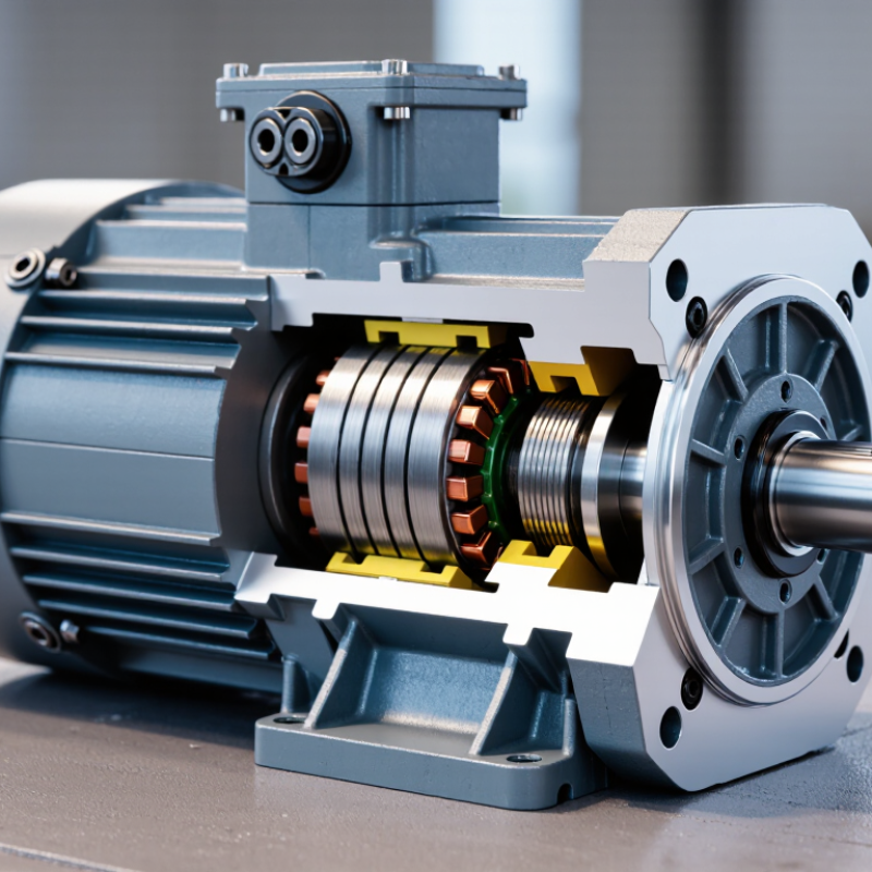
An interior permanent magnet synchronous reluctance motor, or IPM SynRM, combines buried rotor magnets with a reluctance-based rotor design. Its stator carries windings that create a rotating magnetic field when supplied with alternating current. The rotor follows that field and turns at synchronous speed. No brushes are needed.
Two effects produce torque. The magnets provide magnetic flux, while the rotor’s shape creates different magnetic reluctance along its direct and quadrature axes. The rotor tends to align its lower-reluctance path with the stator field. The distinction is not always tidy. In practice, the balance between magnet torque and reluctance torque depends on rotor geometry and operating conditions.
A drive controller adjusts current in the stator windings to manage torque and speed. It coordinates current along the motor’s d and q axes, helping use both torque-producing effects. Careful control matters. A poorly chosen current balance can increase heating or reduce efficiency. Magnet placement, rotor barriers, and steel bridges also influence performance. These details shape the motor’s torque, speed range, and response under changing loads. Designers must balance them; one geometry rarely excels at everything.
An IPM SynRM combines permanent-magnet torque with synchronous-reluctance torque. Its stator has a laminated steel core, slots, and three-phase copper windings. When an inverter supplies controlled current, the windings create a rotating magnetic field. The stator is familiar; the rotor is where this design gets interesting.
The rotor is built from stacked steel laminations. Permanent magnets sit inside it, rather than on its surface, while shaped flux barriers guide magnetic flow through the steel. These barriers create paths with different magnetic reluctance, helping the rotor align with the stator field. The magnets add torque, and the steel structure contributes reluctance torque. Small parts matter. A narrow air gap and accurately placed magnets help maintain consistent magnetic forces.
The International Energy Agency’s 2011 report, Energy-Efficiency Policy Opportunities for Electric Motor-Driven Systems, estimates that motor-driven systems use 43–46% of global electricity. That figure gives designers a practical reason to study motor construction, not just nameplate efficiency. Still, this rotor is not magic: magnet position, lamination quality, and cooling all affect performance. A cutaway drawing can make the barriers look simple; manufacturing tolerances are less forgiving.
An IPM SynRM rotor combines buried permanent magnets with shaped iron paths and flux barriers. In the stator, three-phase current creates a rotating magnetic field. The rotor follows that field, but two effects help produce torque. They work together.
Reluctance torque comes from the rotor’s uneven magnetic resistance. Its iron paths guide magnetic flux more easily in some directions than others. The rotor tends to align its low-reluctance path with the stator field, much like a metal piece settling into a preferred position. That alignment produces torque even without relying on magnet strength alone. The effect depends on rotor geometry and the timing of stator current.
Permanent-magnet torque comes from interaction between the buried magnets’ flux and the stator field. The magnets provide rotor flux, while controlled current creates the force that turns the shaft. A drive adjusts the current angle so reluctance and magnet torque can reinforce each other. Their balance changes with speed, load, and motor design. The split is useful to explain, but never perfectly clean in a real machine. That detail matters. Magnet placement, heating, and manufacturing tolerances can shift performance, so calculated torque is not always the whole story.
Reluctance and permanent-magnet torque are produced together in an interior permanent-magnet synchronous reluctance motor.
How to read this: The permanent magnets contribute torque that varies approximately with sin(δ), while rotor saliency contributes reluctance torque that varies approximately with sin(2δ). Their sum is the illustrative total torque. Values are a conceptual example, not measured motor data; actual torque depends on motor design and operating conditions.
An interior permanent magnet synchronous reluctance motor combines two sources of torque. Its rotor’s shaped iron paths create reluctance torque, while buried magnets add magnetic torque. An inverter controls the current supplied to the stator windings, coordinating it with rotor position. The balance between the two torque sources changes with speed and load.
At low speeds, the controller can apply strong current to produce starting and pulling torque. A position sensor or sensorless estimator helps align the magnetic field with the rotor. That alignment matters. Poor estimates can cause vibration, noise, or lost torque, especially during a quick start. Current limits also protect the windings from overheating.
As speed rises, the inverter approaches its voltage limit. The controller then adjusts the current vector, often weakening the effective magnetic field so the motor can run faster without exceeding that limit. This may reduce available torque. Not always. The result depends on motor design, load, cooling, and control settings. Engineers should check performance across the actual operating range, not just at rated speed; small changes in temperature can shift resistance and affect control accuracy.
An interior permanent-magnet synchronous reluctance motor (IPM SynRM) combines torque from embedded permanent magnets with reluctance torque created by the rotor’s magnetic saliency. The speed zones below are illustrative and expressed relative to base speed; actual limits depend on the motor, inverter, cooling system, and application.
| Operating region | Typical speed reference | Torque and power behavior | How torque is produced | Typical control approach | Main operating considerations |
|---|---|---|---|---|---|
| Standstill and very low speed | 0 to a low fraction of base speed | High torque can be available at low speed, subject to current, thermal, and inverter limits. Mechanical output power is low near standstill. | Magnet torque and reluctance torque can both contribute. The rotor’s embedded magnets also provide a magnetic position signal that can assist position estimation, depending on the control method. | Field-oriented control regulates the motor’s direct-axis and quadrature-axis currents. At or near zero speed, sensorless position estimation may be less reliable, so some systems use a position sensor or specialized estimation methods. | Continuous high torque at low speed can cause substantial winding and inverter heating because there is little or no shaft-driven cooling in many applications. |
| Low-to-medium speed | Below base speed | Approximately constant-torque operation is common when current and temperature limits are not exceeded. | The controller selects current components to use both the permanent-magnet flux and rotor saliency. Their relative contributions vary with motor design and operating point. | Maximum-torque-per-ampere (MTPA) control is commonly used to produce requested torque with an efficient current vector, while current feedback maintains the commanded values. | Current limits, winding temperature, and magnetic saturation constrain torque. MTPA settings are motor-specific and are usually based on characterization or a motor model. |
| Near base speed | Approaching base speed | Torque may begin to fall if the inverter reaches its available voltage limit. Output power can continue to rise toward the constant-power region. | Both torque-producing mechanisms remain available, but the inverter’s voltage capability increasingly affects which current vectors can be used. | The controller coordinates current regulation with voltage limiting. It may transition from MTPA operation toward field-weakening control. | Base speed is the point at which rated voltage and operating conditions typically begin to constrain further speed increases; it is not a universal fixed value. |
| Field weakening | Above base speed, within the designed operating range | Torque generally decreases as speed rises. A motor may operate over an approximately constant-power range, but the range and power level are design-dependent. | Negative direct-axis current is commonly used to reduce the effective air-gap flux and keep the required voltage within the inverter’s limit. This uses some of the available current capacity. | Field-weakening control adjusts the current vector to satisfy voltage and current limits while meeting the torque request where possible. | More field-weakening current can reduce torque-producing current capacity and increase losses. Demagnetization limits, rotor stress, and temperature must also be respected. |
| High-speed operation | Above the field-weakening transition, up to the specified maximum speed | Available torque continues to decline as speed increases; operation may become limited by voltage, current, power, or mechanical constraints. | Reluctance torque remains part of the motor’s torque production, while the controller balances flux reduction and torque-producing current within safe limits. | Advanced drives may use voltage-constrained optimization, such as maximum-torque-per-voltage strategies, together with speed and current limiting. | The allowable maximum speed is set by the complete motor-drive system. Rotor mechanical integrity, bearing limits, losses, cooling, and inverter capability are important constraints. |
| Regenerative braking | During deceleration or when the load drives the motor | The motor can produce braking torque and convert mechanical energy into electrical energy. The amount of recoverable energy depends on the drive and system. | Torque is controlled by changing the current vector so that electromagnetic torque opposes rotation; magnet and reluctance effects both contribute. | A bidirectional inverter controls braking current and manages the DC-link voltage. Regenerated energy may be returned to a compatible supply or stored, depending on system design. | Braking capability is limited by current, voltage, temperature, and the energy-absorption capacity of the supply or storage system. |
An IPM SynRM combines permanent magnets embedded in its rotor with a reluctance-based design. The magnets provide additional torque, while the rotor’s shaped magnetic paths help it turn efficiently. Its performance depends on rotor geometry, the inverter, and operating speed. That matters. At partial loads, a well-matched motor can use less energy than some conventional induction motors. However, actual savings vary with the drive settings and the machine’s duty cycle. Thermal limits also need attention, especially during sustained high-torque operation.
These traits suit pumps, fans, and compressors, where motors often run for long periods. In a pump room, smoother speed control can help match water flow to changing demand. Machine tools and industrial conveyors can benefit from responsive torque and a compact motor package. IPM SynRM designs are also used in some electric vehicle traction systems, where efficiency and power density are important. Not always. A motor that performs well on a test bench may disappoint if it is poorly sized or paired with an unsuitable drive. Engineers should compare load profiles, cooling needs, noise, and control requirements before selecting one. The trade-offs deserve a closer look.