An electric motor does not use one universal magnet. Its design decides the answer. Many permanent-magnet motors use neodymium-iron-boron, or NdFeB, magnets. Ferrite magnets offer a lower-cost alternative, while samarium-cobalt magnets suit some high-temperature applications. Other motors, including many induction motors, create magnetic fields electrically and contain no permanent magnets.
The U.S. Department of Energy’s 2023 Critical Materials Assessment identifies rare earth elements as important materials in high-performance permanent magnets. The U.S. Geological Survey’s Mineral Commodity Summaries 2024 estimates 2023 global rare-earth mine production at about 350,000 metric tons of rare-earth-oxide equivalent. That figure describes mined material, not magnet output. Still, it shows the scale of the upstream supply behind some motor designs. The distinction matters.
Choosing an electric motor magnet means balancing more than strength. Engineers consider operating temperature, available space, cost, corrosion protection, and the motor’s duty cycle. A compact traction motor may favor NdFeB’s high magnetic performance. A fan or pump may use a different design where price or operating conditions matter more. The best answer depends on the job. It is easy to overlook how much the rotor, cooling system, and control strategy affect that choice. Reports can guide the discussion, but they cannot replace a motor’s actual specifications.
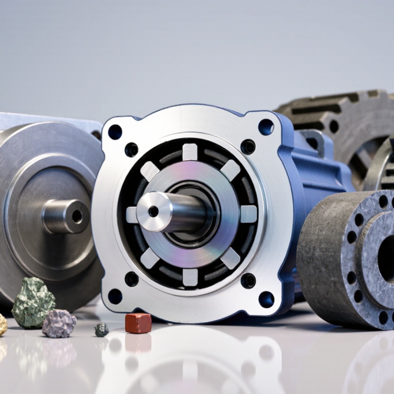
Magnets create the forces that make an electric motor turn. In many motors, magnetic fields interact with electric current in coils, producing torque around a shaft. The field must keep changing direction or position as the motor runs. Otherwise, the rotor may stop at a point where the forces balance. The gap matters. A small change in that gap can affect torque, heat, and efficiency.
The magnet type depends on the motor’s design. Permanent magnets, often made from ferrite or rare-earth materials, provide a steady field without continuous current. They are common in compact motors, including many brushless designs. Other motors use electromagnets: current flowing through wound coils creates their magnetic fields. In induction motors, the stator’s rotating field induces current in the rotor, which then produces its own field. So, not every electric motor contains a permanent magnet.
Motor designers balance strength, cost, temperature tolerance, and size. A strong magnet can help produce more torque in a smaller package, but heat may weaken some materials. The surrounding steel also shapes and guides magnetic flux, so the magnet alone does not determine performance. It is tempting to name one “best” magnet, but that overlooks the motor’s duty cycle and operating conditions. Heat changes things. A motor running briefly in a fan faces different demands from one powering a vehicle through repeated acceleration.
Permanent magnets are common in compact, high-efficiency motor designs. Neodymium-iron-boron (NdFeB) magnets provide strong magnetic fields in a small volume, making them useful in many traction and industrial motors. Ferrite magnets cost less and resist corrosion, but usually need more space for comparable output. Samarium-cobalt magnets tolerate heat well, though their cost limits their use. The right choice depends on torque, temperature, size, and budget.
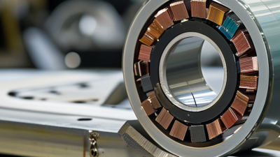
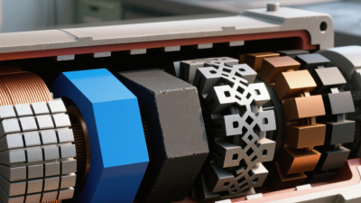
A rotor may carry curved magnets on its surface or bury them beneath its steel laminations. In both layouts, the magnets provide a steady field without continuous electrical current in the rotor. Small details matter: adhesive, rotor sleeves, and heat paths help keep magnets secure and reduce demagnetization risk.
There is a trade-off. The International Energy Agency’s Global EV Outlook 2024 reports nearly 14 million electric car sales in 2023, about 18% of global car sales; this signals rising motor demand, not a specific share for permanent-magnet motors. The U.S. Department of Energy’s 2022 Rare Earth Permanent Magnets supply-chain assessment also identifies NdFeB magnets as important components in advanced technologies.
A common assumption is that stronger magnets always make a better motor. They do not. Design choices can be imperfect, and sometimes a larger, simpler ferrite motor is the wiser fit.
In many electric motors, the magnet is an electromagnet rather than a permanent magnet. Copper wire is wound around an iron core to form a field winding. When current passes through the winding, it creates a magnetic field. The iron guides and strengthens that field, while the coil’s direction determines its poles. That is the core idea.
Field windings can sit in the stator, the stationary part, or in a rotor that turns. In a brushed DC motor, stator windings may provide the field, while current in the rotor interacts with it to produce torque. Other designs use permanent magnets or create a rotating field with stator windings. The arrangement depends on the motor’s design, not just its size. Not quite one-size-fits-all.
Changing the current can change the field’s strength; reversing it can swap the poles. More turns can also affect the field, but extra current brings heat and energy losses. A motor running under load may warm around its casing, though temperature alone does not reveal exactly what is happening inside. The simple explanation leaves out magnetic saturation and control electronics, too. It matters. A field winding is a practical way to make and manage magnetism, but its performance depends on the whole motor.
| Motor type | Magnetic-field source | Where the field is produced | How it works | Common applications |
|---|---|---|---|---|
| Wound-field DC motor | Electromagnets made from copper field windings | Usually the stationary field poles; the armature winding is on the rotor | Current through the field winding creates the stator magnetic field. The armature current interacts with that field to produce torque. | Industrial drives, older traction systems, and applications needing adjustable speed or torque |
| Induction motor | Electromagnets in the stator; rotor current is induced during operation | The stator windings create a rotating field; current flows in the rotor conductors | The rotating stator field induces rotor currents. Their magnetic interaction with the stator field produces torque. A typical squirrel-cage rotor does not use permanent magnets. | Pumps, fans, compressors, and many general-purpose industrial machines |
| Wound-field synchronous motor | Electromagnet supplied by a DC field winding | The field winding is on the rotor; the stator carries AC windings | The rotor winding creates magnetic poles that lock in step with the rotating stator field when the motor is synchronized. | Large industrial drives and installations where power-factor control is useful |
| Permanent-magnet synchronous or brushless DC motor | Permanent magnets, commonly rare-earth or ferrite types | Magnets are mounted in or on the rotor; energized stator windings create the rotating field | The rotor magnets provide a persistent field without a rotor field winding. Electronic control switches stator currents to produce rotation. | Servo systems, appliances, compact tools, and many electric vehicles |
| Switched-reluctance motor | Electromagnets in the stator; the rotor is typically laminated soft magnetic steel | Individually switched stator pole windings generate the magnetic field | Sequentially energized stator poles pull the rotor toward positions of lower magnetic reluctance. The rotor typically has no permanent magnets or windings. | Some pumps, appliances, and applications designed for robust, magnet-free rotors |
In short, many electric motors use electromagnets formed by current-carrying windings. Some designs also use permanent magnets, while others produce rotor magnetism through induced current or use a magnetically responsive iron rotor.
The motor’s operating principle sets the first constraint. An induction motor creates its rotor field through induced current, so it needs no permanent magnets.
No magnets needed.
Synchronous-reluctance motors also rely on rotor shape rather than magnets, making them useful where material cost or supply matters more than maximum torque density.
Permanent-magnet motors use magnets to create a steady rotor field. Sintered neodymium-iron-boron magnets suit compact designs that need strong torque, such as traction or small servo motors. Ferrite magnets cost less and avoid rare-earth elements, but their weaker magnetic output can mean a larger motor.
Heat matters.
Engineers check operating temperature, rotor speed, and demagnetization risk before selecting a grade.
The trade-off is practical, not purely theoretical. A high-torque design may favor rare-earth magnets, while a cost-sensitive pump or fan may work well with induction or ferrite-based designs.
The International Energy Agency’s 2011 report, Energy-Efficiency Policy Opportunities for Electric Motor-Driven Systems, estimated that motor-driven systems use about 45% of global electricity.
That scale makes efficiency important, but a magnet choice alone does not guarantee it; control electronics, cooling, and load profile matter too.
There is no universal best magnet, and early design estimates can miss real operating heat.
Magnet selection begins with the motor’s job, not a material label. A compact e-bike drive may favor neodymium magnets because they provide strong flux in limited space. A large industrial motor may accept heavier ferrite magnets when lower material cost matters. The choice also depends on rotor geometry: each magnet must fit securely and provide a useful field across the air gap. Small gaps matter.
Temperature can change the decision. Neodymium magnets may lose strength if a motor runs hotter than their grade permits, so engineers consider winding heat, cooling, and overload duration. Samarium-cobalt often tolerates higher temperatures and resists corrosion, but it costs more and can be brittle during handling. Ferrite handles heat well, yet its lower magnetic strength may require a larger rotor. That trade-off matters.
Operating conditions matter as much as peak power. Frequent starts, abrupt current changes, vibration, and reverse magnetic fields can increase demagnetization risk. Designers compare coercivity, expected service life, and temperature margins, then test prototypes under realistic loads. Moisture and salt near a coastal installation may call for protective coatings or a more corrosion-resistant material. Coatings can chip. I would not choose from a catalog strength figure alone; actual cooling and assembly tolerances can undermine a neat calculation.