Choosing a permanent magnet rotor can reshape how your business uses energy, space, and maintenance time. In practical terms, permanent magnets create the rotor’s magnetic field without continuous electrical excitation. This design can reduce rotor losses and improve motor efficiency, especially under changing loads.
Dr. Thomas A. Lipo, a respected motor-technology professor and author, describes the principle as “a synchronous motor with permanent magnets embedded in or attached to the rotor.” His work gives engineers a reliable foundation for evaluating this technology. Yet technical theory must meet real operating conditions. A factory may gain lower heat generation, quieter operation, and a smaller motor footprint. A conveyor running for thousands of hours can make small efficiency gains financially meaningful.
The benefits are not automatic. They depend on speed, torque, duty cycle, temperature, and control quality. Magnet performance can also decline when excessive heat enters the rotor. That detail is easy to overlook. It should not be.
A careful business decision begins with measurements. Record current energy use, operating hours, load variations, and service costs. Then compare those figures with the expected performance of a permanent magnet rotor. Ask about cooling, magnet protection, drive compatibility, and repair procedures. Supplier claims deserve verification through test data and application references.
There is room for honest uncertainty. A permanent magnet rotor may cost more initially. Its return depends on how intensively the equipment operates. For many manufacturers, however, improved efficiency, compact construction, and reduced maintenance can support stronger long-term value. The right choice is evidence-based, not fashionable.

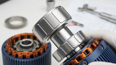
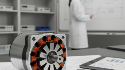
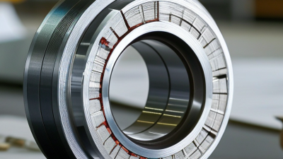
A permanent magnet rotor is the rotating core of a motor that uses fixed magnetic fields instead of energized rotor windings. Rare-earth or ferrite magnets sit inside or on the rotor’s steel body. When stator windings create a rotating magnetic field, the rotor follows it and produces torque.
This design removes rotor copper losses. It can also deliver high efficiency at partial loads, especially in pumps, fans, compressors, and electric vehicles. The International Energy Agency reports that electric motor systems consume roughly half of global electricity. Small efficiency gains therefore matter across large equipment fleets. The U.S. Department of Energy also identifies high-efficiency motors and adjustable-speed drives as practical industrial energy-saving measures.
The rotor needs an inverter for controlled starting and speed regulation. It may also require sensors, thermal protection, and careful demagnetization control. That adds engineering work. Not every application benefits equally. High temperatures, shock loads, and magnet material costs can change the decision. A factory trial should measure actual load patterns, bearing temperatures, vibration, and electricity use. Simple laboratory ratings can mislead.
In my experience, the best results come from matching rotor design with the duty cycle. The answer is not always “permanent magnet.” That deserves honest review.
A permanent magnet rotor works by turning magnetic force into controlled rotation. Permanent magnets are fixed inside or on the rotor. The stator creates a rotating magnetic field through three-phase current. Unlike an induction rotor, it does not need induced current to produce torque. This reduces rotor losses and helps maintain efficiency at changing loads. The drive system must synchronize current and rotor position accurately. Sensors or sensorless control software usually provide that timing.
The energy impact can be significant. The International Energy Agency reports that electric motor systems consume about 53% of global electricity. Even small efficiency gains therefore matter across factories, pumps, fans, and compressors. Industry studies commonly place permanent magnet synchronous motors in IE4 or IE5 efficiency classes, depending on design and operating conditions. The European Commission’s motor ecodesign research also identifies permanent magnet technology as a route toward higher efficiency.
In practical use, imagine a conveyor starting under load. The rotor produces torque immediately, with little electrical waste inside the rotor. Less heat may mean smaller cooling requirements. But the advantage is not automatic. Magnets can raise purchase and recycling costs. Control settings may also reduce performance. I have seen efficiency claims weaken when motors run far below rated load. A proper load profile matters. So does thermal testing. Check measured data, not only the nameplate.
| Dimension | Permanent Magnet Rotor | Business and Operating Significance |
|---|---|---|
| Basic Operating Principle | Permanent magnets create a constant magnetic field on the rotor. The stator’s rotating magnetic field pulls the rotor into synchronous rotation. | The rotor does not require electrical current to create its magnetic field, reducing rotor excitation losses and simplifying the electromagnetic design. |
| Rotor Electrical Losses | Ideally close to zero during steady operation because no rotor winding current is required. | Lower internal heat generation can support higher efficiency and reduce the cooling demand compared with an equivalent wound-rotor design. |
| Typical Motor Efficiency | Commonly about 90%–97% for efficient industrial permanent-magnet motor systems, depending on power, speed, cooling, and load. | Higher efficiency can reduce electricity consumption, especially in equipment that operates for long hours or at high utilization. |
| Speed Regulation | Runs at synchronous speed when controlled by a suitable variable-frequency drive. Speed is determined primarily by supply frequency and pole count. | Provides accurate and repeatable speed control for pumps, fans, compressors, conveyors, machine tools, and automated production equipment. |
| Slip | Approximately zero in steady-state synchronous operation. | Eliminating normal operating slip can improve speed accuracy and avoid the rotor copper losses associated with many induction motor designs. |
| Power Factor | Often high when the motor and drive are correctly designed; the exact value depends on motor geometry, control settings, and operating load. | A higher power factor can reduce reactive-current demand and help improve the utilization of electrical distribution equipment. |
| Power Density | Typically higher than that of a comparable conventional motor because torque-producing magnetic flux is supplied by permanent magnets. | A more compact motor can reduce equipment footprint and may lower the mass of drive systems where space or weight is limited. |
| Torque Production | Electromagnetic torque is produced by interaction between the rotor’s permanent-magnet field and the stator’s controlled magnetic field. | High torque density is useful for direct-drive systems and applications that require strong low-speed performance. |
| Starting and Control | Many permanent-magnet motors require an inverter or variable-frequency drive for controlled starting and synchronization. | Electronic control enables soft starting, adjustable speed, regenerative operation, and protection functions, but adds drive-system requirements. |
| Thermal Management | Rotor winding losses are avoided, but heat can still be generated in stator windings, bearings, magnets, and other components. | Lower rotor heating may improve thermal performance, but correct cooling and temperature monitoring remain important for reliable operation. |
| Operating Temperature | Magnet temperature must remain within the specified design limit to prevent irreversible demagnetization. Many industrial magnet grades are designed for elevated temperatures, but limits vary. | Proper ventilation, overload protection, and thermal design are essential when motors operate in hot environments or under frequent overload conditions. |
| Maintenance Requirements | No rotor brushes, slip rings, or rotor excitation supply are normally required. | Fewer wear-related electrical components can reduce routine maintenance, although bearings, insulation, sensors, and the drive still require inspection. |
| Energy-Saving Potential | Energy savings are most significant under continuous operation, variable-load conditions, and applications where efficient speed control is possible. | Lower energy use can reduce operating costs and support efficiency targets. Actual savings depend on duty cycle, load profile, motor sizing, and drive settings. |
| Noise and Vibration | Can operate smoothly because there is no normal slip between the rotor field and the rotating stator field, although inverter switching and mechanical design also affect noise. | Potentially lower vibration and acoustic output can improve workplace conditions and reduce stress on connected equipment. |
| Common Industrial Applications | Variable-speed pumps, fans, compressors, conveyors, elevators, robotics, machine tools, electric vehicles, and high-efficiency process equipment. | Suitable when energy efficiency, compact size, precise speed control, high torque density, or reduced maintenance is more important than the lowest initial system cost. |
| Key Design Consideration | Magnet material, rotor topology, pole count, cooling method, drive compatibility, demagnetization margin, and mechanical strength must be selected together. | A complete motor-and-drive evaluation is necessary because performance depends on the whole system rather than the rotor alone. |
| Important Limitation | Permanent magnets may be sensitive to excessive temperature, fault current, mechanical shock, or unsuitable control conditions. | Appropriate protection, thermal monitoring, short-circuit management, and qualified maintenance help preserve performance and service life. |
A permanent magnet rotor can turn motor efficiency into a measurable business advantage. The International Energy Agency reports that electric motor systems consume roughly half of global electricity. Even a small efficiency improvement can reduce monthly operating costs in pumps, fans, compressors, and conveyors.
Permanent magnet rotors avoid many rotor copper losses found in conventional induction motors. This design can deliver high efficiency across a wider operating range, especially during partial-load periods. The U.S. Department of Energy identifies motor-driven equipment as responsible for more than half of industrial electricity use. Lower losses also mean less heat inside the motor. In a factory, that may reduce cooling demand and support longer bearing and insulation life. It feels practical: fewer hot surfaces, steadier output, and less wasted energy.
The business case depends on the application. A permanent magnet motor usually needs a suitable drive, careful commissioning, and trained maintenance staff. The initial purchase cost may be higher. Payback is not automatic. A poorly sized rotor or incorrect control setting can weaken the expected savings. Still, field assessments often reveal strong opportunities where motors run continuously, such as water treatment or material handling. The European Commission’s motor-efficiency studies also emphasize system-level savings, not motor efficiency alone.
Measure load profiles before investing, then compare energy use, downtime, service access, and replacement costs. That step is sometimes skipped. It should not be.
Choosing a permanent magnet rotor starts with your machine’s actual duty, not a brochure’s peak efficiency. In field evaluations, the load profile often matters more than rated power. Record torque, speed, starting frequency, and daily operating hours. A rotor for steady production may not suit rapid acceleration. Check whether the motor runs frequently at low speed. Efficiency can fall outside its preferred range. Small details matter.
Thermal behavior deserves close attention. Permanent magnets can lose performance when exposed to excessive heat. Ask for temperature limits, cooling requirements, and test conditions. Confirm compatibility with the drive, feedback system, shaft design, and supply voltage. Mechanical fit is equally important. Review inertia, balancing tolerance, bearing loads, enclosure protection, and vibration data. A compact rotor may reduce losses, yet increase cooling or manufacturing demands. Paper calculations rarely show that trade-off clearly.
Selection should include lifecycle cost, service access, and technical support. Compare energy savings with purchase price, installation time, spare-part availability, and inspection intervals. Request measured data from a test method you can understand and reproduce. Independent verification adds confidence when figures seem unusually precise. Do not ignore material sourcing or end-of-life handling. These factors affect reliability and procurement risk. One weakness remains: operating data is often incomplete. Use conservative assumptions, then revisit them after a pilot run. A rotor that survives real starts, heat cycles, and dust is more valuable than one that only wins a spreadsheet.
A permanent magnet rotor can improve efficiency, but successful results depend on careful implementation. Start by matching the rotor’s torque, speed, and temperature limits with the driven equipment. Review the motor’s technical documentation and applicable electrical standards before installation. Record shaft dimensions, coupling details, and the required air gap. Small errors matter.
During installation, use calibrated tools and keep the rotor clean and dry. Align the shaft carefully to reduce vibration and bearing loads. Never place loose steel tools near exposed magnets. Connect the drive system according to the approved wiring diagram, including grounding and protection devices. Confirm insulation resistance before energizing the motor. A slow commissioning ramp can reveal unusual noise, heat, or unstable current. Stop immediately if readings change sharply.
Maintenance should combine scheduled inspections with operating data. Check vibration, bearing temperature, current balance, and rotor speed at regular intervals. Trend these readings instead of relying on one inspection. Keep cooling passages free from dust, oil, and compacted debris. Inspect seals and couplings for wear. Permanent magnets usually need little service, but excessive heat or severe mechanical impact can reduce performance. Do not disassemble the rotor without proper lifting equipment and technical guidance. Keep records. An overlooked alignment issue may appear months later as bearing damage, so review the original installation when symptoms return.