

In numerous motion control applications, permanent magnet DC motors play a pivotal role. When it comes to implementing control systems for motion, small DC motors often take precedence over their AC counterparts due to their simplicity. Small DC motors find extensive use in scenarios requiring precise control of speed, torque, or position.
Two primary types of small DC motors are commonly employed: Brushed motors and Brushless motors, often referred to as BLDC motors. These names hint at their fundamental differences. Brushed motors rely on brushes for commutation, while Brushless motors replace this mechanical commutation with electronic control.
In many applications, choosing between a brushed and a brushless small DC motor depends on specific requirements, as both operate based on the principles of magnetic attraction and repulsion between coils and permanent magnets. Each has its advantages and disadvantages, influencing the choice based on the application's needs.
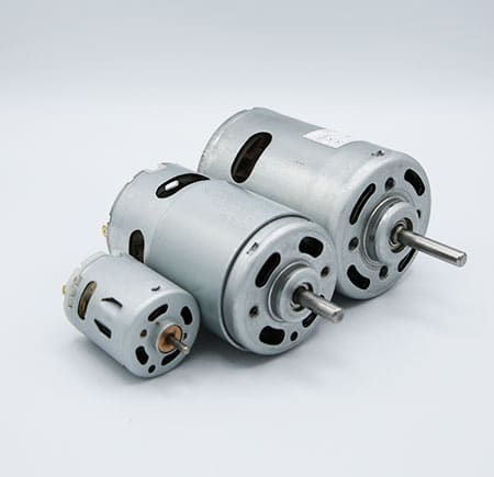
Brushed DC Motors
Small DC motors employ wound wire coils to create a magnetic field. In brushed motors, these coils are free to rotate and form the rotor of the small DC motor. Typically, the coils are wound around an iron core, although some brushed motors are "coreless," featuring self-supported windings.
The stationary part of the motor is known as the "stator," which relies on permanent magnets to provide a fixed magnetic field. These magnets are usually positioned on the inner surface of the stator, outside of the rotor.
To generate torque and spin the rotor within the small DC motor, the magnetic field of the rotor must continually rotate to attract and repel against the stator's fixed field. This rotation is achieved using a sliding electrical switch, consisting of a commutator (usually segmented and mounted to the rotor) and fixed brushes (mounted to the stator).
As the rotor turns, the commutator switches different sets of rotor windings on and off, causing the rotor coils to be alternately attracted and repelled by the stator's fixed magnets, resulting in rotor rotation.
However, due to mechanical friction between the brushes and commutator, and their nature as electrical contacts (which cannot be lubricated), these components experience mechanical wear over the motor's lifespan. This wear eventually reaches a point where the motor becomes nonfunctional. Some brushed motors, especially larger ones, have replaceable brushes made of carbon to maintain contact. Nevertheless, the commutator may also wear out, meaning a small DC motor replacement will be needed.
To drive a brushed motor, a DC voltage is applied across the brushes, allowing current to flow through the rotor windings and initiate motor rotation.
In cases where only unidirectional rotation is needed without the need for speed or torque control, no additional drive electronics are required. The DC voltage is simply turned on or off to start or stop the small DC motor. This is commonly seen in low-cost applications like motorised toys. Reversing direction can be achieved using a double-pole switch.
For finer control over speed, torque, and direction, an "H-bridge" composed of electronic switches (such as transistors, IGBTs, or MOSFETs) is used to enable bidirectional motor operation. This allows voltage to be applied to the motor in either polarity, resulting in reversible rotation. Motor speed or torque can be adjusted through pulse width modulation (PWM).
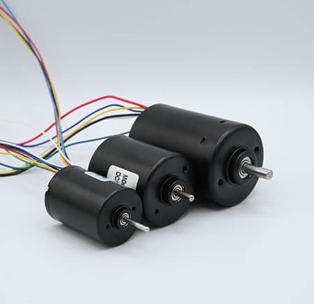
Brushed DC Motors
Brushless DC motors operate on the same magnetic attraction and repulsion principles as brushed motors but differ in construction. Instead of employing a mechanical commutator and brushes, electronic commutation is used to rotate the stator's magnetic field within the small DC motor, necessitating active control electronics.
In a brushless motor, the rotor is equipped with permanent magnets, while the stator features windings. Brushless motors can be designed with the rotor either on the inside (as shown earlier) or on the outside of the windings, often referred to as an "outrunner" motor.
The number of windings in a brushless motor is referred to as the number of phases, with three-phase brushless motors being the most common. Smaller cooling fans may use only one or two phases.
These three windings in a brushless motor can be connected in either a "star" or "delta" configuration, both having three wires connecting to the small DC motor, with identical drive techniques and waveforms.
Small DC motors with three phases can vary in magnetic configurations, known as poles. The simplest 3-phase motors have two poles, meaning the rotor has a single pair of magnetic poles – one North and one South. Motors can also be designed with more poles, requiring more magnetic sections in the rotor and additional windings in the stator. Higher pole counts can offer enhanced performance, though lower pole counts are often preferred for very high-speed applications.
To drive a three-phase brushless motor, each of the three phases must be independently driven to either the input supply voltage or ground. This is achieved using three "half bridge" drive circuits, each comprising two switches, which can be bipolar transistors, IGBTs, or MOSFETs, depending on the voltage and current requirements.
Several drive techniques can be employed for three-phase brushless motors. The simplest is known as trapezoidal, block, or 120-degree commutation. Trapezoidal commutation somewhat resembles the commutation method used in a DC brushed motor. In this scheme, at any given moment, one of the three phases is connected to ground, one is left open, and the other is driven to the supply voltage. If speed or torque control is required, the phase connected to the supply is typically pulse width modulated (PWM). Due to abrupt phase switching at each commutation point while the rotor rotation remains constant, some torque variation (known as torque ripple) occurs during motor rotation.
For higher performance, alternative commutation methods can be employed. Sine or 180-degree commutation continuously drives current through all three motor phases, each shifted by 120 degrees from the others. This approach minimises torque ripple, as well as reduces acoustic noise and vibration, making it suitable for high-performance or high-efficiency applications.
To properly rotate the field, the control electronics must accurately determine the physical position of the rotor's magnets relative to the stator. Hall sensors are commonly used for this purpose, mounted on the stator. As the magnetic rotor rotates, these Hall sensors detect its magnetic field, enabling the drive electronics to pass current through the stator windings in a sequence that propels the rotor.
For trapezoidal commutation, simple combinational logic can be used when employing three Hall sensors, eliminating the need for sophisticated control electronics. In contrast, more advanced commutation methods like sine commutation necessitate more sophisticated control electronics, often incorporating a microcontroller.
Besides Hall sensors, various sensorless methods can determine rotor position. The simplest involves monitoring the back electromotive force (EMF) on an inactive phase to sense the rotor's magnetic field relative to the stator. A more complex control algorithm known as Field Oriented Control (FOC) calculates the position based on rotor currents and other parameters. FOC typically requires a powerful processor due to the numerous calculations that must be executed quickly, making it costlier compared to simpler trapezoidal control.
Advantages and Disadvantages of Brushed and Brushless Motors
The choice of small DC motor when choosing between a brushed and brushless option depends on specific application requirements. Below are key factors to consider:

Lifetime:
- Brushed Motors: Brushes and commutators in brushed motors wear out over time. Carbon brushes are sacrificial and often replaced periodically. The copper commutator also wears out, leading to motor failure.
- Brushless Motors: Brushless motors have no moving contacts like brushes and commutators, so they do not suffer from wear-related issues, offering longer lifespans.

Speed and Acceleration:
- Brushed Motors: Rotational speed in brushed motors can be limited by brushes, commutators, and rotor mass. High speeds may cause erratic brush-to-commutator contact and arcing.
- Brushless Motors: Brushless motors can achieve higher speeds due to the absence of mechanical limitations like brushes and commutators. They can also provide better acceleration rates, especially when equipped with rare earth magnets, though this increases cost.

Electrical Noise:
- Brushed Motors: Brushed motors produce electrical noise due to the constant opening and closing of the brushes as current flows through the inductive rotor windings.
- Brushless Motors: Brushless motors generate less electrical noise since there are no brushes and commutators involved in the switching process.

Acoustic Noise:
- Brushed Motors: Brushed motors are "hard switched," resulting in torque ripple, which can cause vibration and mechanical noise, particularly at low rotor speeds.
- Brushless Motors: Brushless motors can be controlled to transition current between windings more smoothly, reducing torque ripple and minimising mechanical noise.

Cost:
- Brushed Motors: Traditional brushed motor technology is mature and cost-effective, primarily due to the simplicity of manufacturing. However, costs may rise as demand shifts towards brushless motors.
- Brushless Motors: Brushless motors initially require more sophisticated electronics, making them more expensive. Nevertheless, the decreasing cost of electronics, such as microcontrollers, is making brushless motors increasingly attractive.

Summary
As the cost of brushless motors and associated electronics continues to decrease while offering better performance, they are gaining popularity in various applications. However, there are still scenarios where brushed motors remain a practical choice.
A notable example of this transition can be observed in the automotive industry. By 2020, most small DC motors running continuously while a vehicle operates, such as pumps and fans, had shifted from brushed to brushless motors due to their enhanced reliability. The added cost of the small DC motor and electronics was offset by reduced field failures and maintenance requirements.
Conversely, small DC motors used infrequently in automobiles, such as those adjusting power seats and windows, predominantly remain brushed motors. The rationale behind this decision lies in the limited runtime of these motors over a car's lifespan, making motor failure highly unlikely.
As brushless motors become more cost-effective and their electronics more advanced, they are progressively penetrating applications traditionally dominated by brushed motors. For instance, high-end cars have begun adopting brushless motors for seat adjustments, primarily because they produce less acoustic noise.
| Are you looking for a similar solution for your product? Call our friendly team on +44 (0) 1460 72000 |


